Mutliplatform/Multi OS Oscilloscope/Signal Generator

Story
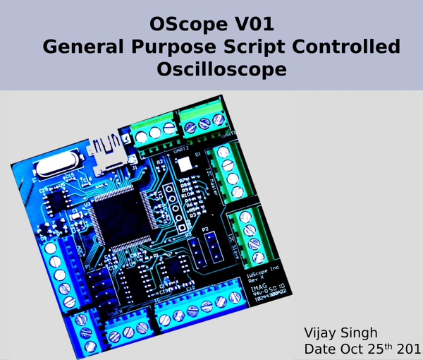
Do you have an old, unused Raspberry PI/Linux/Windows machine? Make use of it with our Multi OS Oscilloscope device which is versatile and supported on multiple platforms.
This device is an extremely helpful tool for electronics engineers or people who want to automate sequences of analog-digital output.
OScope Plugin Feature
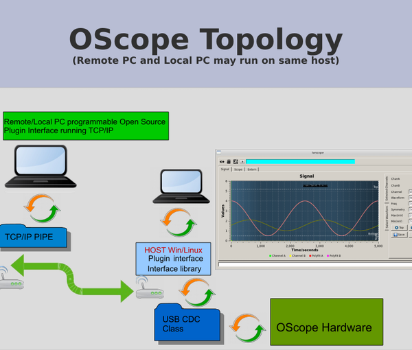
- Simple TCP/IP pipe-based plugin interface which is written in “C”, the plugin may operate on the same host, or it can be a remote computer. All features of the plugin interface, sample code have been provided.
- The plugin is a simple client socket code that can be replaced with Python/C#/Labview API, as per the need. (At some point support for adding python2.x/3.0 and C# with examples will be provided).
- Multiplatform (ARM, Linux, x86, Windows). Raspberry Pi/Beagle bone Black/Freescale/Windows/Intel Ubuntu and XP/7/8.
- The plugin may control all parts of GUI with interface including message display/graph/signal with lots of feedback, which makes it useful for production floor calibration utility.
- Field firmware is upgradeable without the need for a programmer.
- Flexible framework and powerful programmable intuitive and simple interface, and best of all it works on most operating systems.
Use Cases
- Handy tools which can perform multifunctional, dual-channel, signal generators or oscilloscope devices can be quickly customized for close loop system testing needs.
- Up to 1 MHz when used with other 10-bit ADC (Internal PIC32).
- Easily integrable with python script for doing complex tasks.
- Field firmware is upgradeable without ICD/JTAG programmer device.
- Flexible framework and powerful programmable intuitive and simple interface, and best of all it works on most operating systems.
- The plugin feature enables users to communicate with an array of devices.
Features
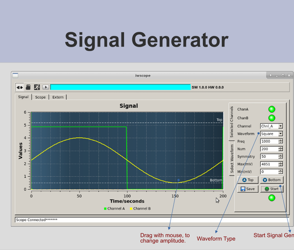
- Dual-channel, independent multifunctional generator.
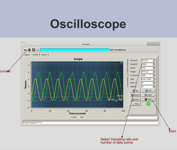
- A dual-channel Oscilloscope may operate parallel to the signal generator.
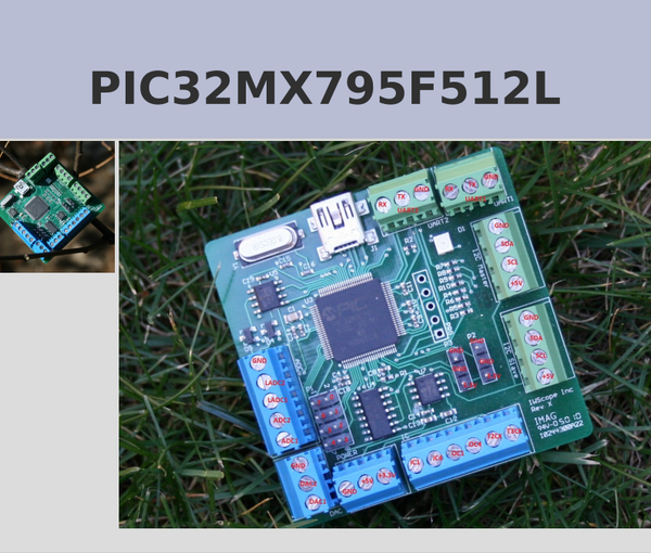
- Twin two I2C Master which (7-bit addressing/400KHz Clock).
- Read/Write 21 GPIO from plugin interface.
- Single-channel 32bit PWM input capture for measuring pulse width modulation very accurately.
- Single-channel output capture can be controlled by a plugin interface.
- Dual ADC/DAC can capture and generate continuous signals.
- Flexible communication library functions are well documented along with GUI/console. Sample code provided.
- Dual-channel TTL UART may receive and transmit data up to 460800 baud.
Features
- Oscilloscope (Dual-channel 12-bit 5V Max, Max 100KHz).
- Signal generator (Dual-channel 12-bit 5V Max, Max 100KHz).
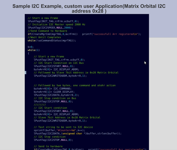
- I2C Master/Slave (5V, Max 400KHz Clock). Sample app included.
- Input capture.
- Single-channel PWM generation.
- Channel digital 3.3V IO.
- Output capture for creating PWM.
- TTL 3.3.V UART (5V Tolerance, up to 460800 baud).
- Direct runtime import signal from csv file via plugin/direct interface.
Possible Use Cases
A powerful tool when implementing iterated real complex automated long sequence of calibration which requires read/write/i2c/uart/gpio/pwm where interaction between sets of operation is heavily interdependent on previous or next.
For example – User A calibrates a magnetic measurement in a feedback loop. Calibration of such a system will require feeding a known calibrated signal and measuring its system output in multiple steps and while varying temperature and other parameters, calibrating such a system manually by using a traditional signal generator and while controlling temperature is a very tedious task with the possibility of human error.
This tool enables you to generate variable signals and capture output while controlling other sequences, which can be done directly using the plugin interface. It also enables the end-user to create his own C++/C#/Qt GUI. The plugin feature has been covered heavily in the next slides.
As a feature of the plugin, a lot of colorful feedback along with log file generation can be added, which reduces the chance of human error.
Using First Time (Linux)
- Open the command prompt on the Linux terminal (Username vs).
- Run a Sudo command $ sudo addgroup vs dialout.
- Run a Sudo command $ sudo addgroup vs plugdev.
- Reboot: Linux Desktop and open a Linux terminal $ prompt.
- $ sudo dmesg -C; clears dmesg buffer.
- Connect USB hardware to Linux machines.
- Enter the $ dmesg command in the terminal.
Running Oscilloscope App
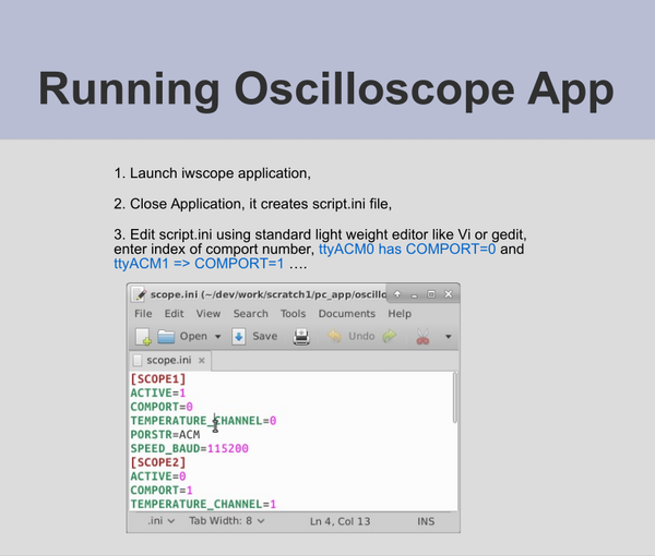
- Launch iwscope application.
- Close application, it creates script.ini file.
- Edit script.ini using a lightweight editor like VI or gedit, enter the index of comport number, ttyACM0 has COMPORT=0 and ttyACM1 => COMPORT=1.
Troubleshooting Linux
- Check if the user has permission to read and write the serial port using minicom or picocom.
- Provided libraries for the following Linux platforms. (Make sure hw/OS matches) – Raspberry Pi (Raspebian), Beagle Bone Black (Debian), Intel x86 x64 (Ubuntu 32 & 64 bit), Intel Edison
Using First Time (Windows)
- Press Windows + R dvmgmnt.msc, open devices.
- Run device manager and locate com port section:
- This com port should disappear and appear as a Scope device disconnected or connected over the USB port.
- The next page shows Edit oscope.ini file, enter the correct COM port.
External Custom Application Integration
- C++ compiled libraries for easy integration with external frameworks. Example – for provided Linux ARM/Intel/Windows x86 x64.
- Sample open-source library interfaces Qt 4.0 code provided as an example.
- Open-source TCP/IP plugin interface example code.
- Fully tested platforms – Windows XP, Windows 7 (32/64), Linux 32/64 (Intelx86, x64, Beagle Bone Black, Raspberry Pi)
How to Upgrade Firmware
- Download the latest firmware for this device. https://github.com/vijayandra/oscopev1
- Connect Rx/TX of UART 1 as shown in the picture, connect a USB device, device maps as HID device.
- Start the boot loader application and browse to the downloaded file and start boot loader. Estimated boot time is around 30 seconds.
- Unplug USB device, remove jumper joining Rx/TX so device does not enter in bootloader mode.
- Start using the device, Oscilloscope application should show a new version of the app when connected.
- The main application does not need any installer. It can be downloaded as a single zipped file.
Limitation/Known Issues
- Because of Microsoft WHQL device certification serial port does not enumerate for Windows 7 x64 bit (Need to disable driver signing enforcement, press F12 during boot up to disable).
- USB 2.0 full speed is speed limitation. The onboard LED is reversed mounted so it does not function.
- Basic Linux/Windows comport configuration is needed to enumerate the com port.
- The use of plug-in features requires basic “C” programming knowledge.
- All examples use the Qt4.0 framework.
- Open-source TCP/IP plug-in interface example code.
How to USE Software
Users may choose to interact with hardware using the following three possible modes:
- Local direct GUI mode (Under this mode user may choose to run a scope that is connected to the host system directly via USB CDC).
- Local Direct Custom Application Plugin Mode (Under this mode user creates application interaction with hardware, types of Qt sample C++ cli application library and header files provided along with support library).
- Remote Plugin Mode (Under this mode user’s custom application interacts via TCP/IP pipes (Port 9999 and 9998 respectively).
Mode #2 and #3 are ideal for creating automated test sequences, Sample C# application also has been provided which generates a waveform, reads GPI, creates PWM and measures PWM.
All libraries and main application are fully tested on Ubuntu (ARM & Intel), Windows (XP, 7, 8).
How to Control Scope/Signal Sampling Freq
User may control sampling freq like example given below:
PIC32 running at 80 MHz (80×1000000/TMR) = 80 KHz, provided the selected (TMRDiv) divider is 0. Similar calculations are applicable for signal generators.
- 0=Main Clock Divided by 1 (Above 80MKhz Clock)
- 1=Main Clock Divided by 4 (Replace 80 with 20, Result 20 KHz)
- 2= Main Clock Divided by 8 (Replace 80 with 10, Result 10 KHz)
- 3=Main Clock Divided by 16
- 4=Main Clock Divided by 32
- 5=Main Clock Divided by 64
- 6=Main Clock Divided by 256
Risks and Challenges
As far as driver, application, and interface libraries are concerned there is no risk as they are fully developed and tested. Board is only good for 0 to 5V signals or scope. One feature which was not described supports a boot loader, which means firmware can be updated from time to time.


Reviews
There are no reviews yet.