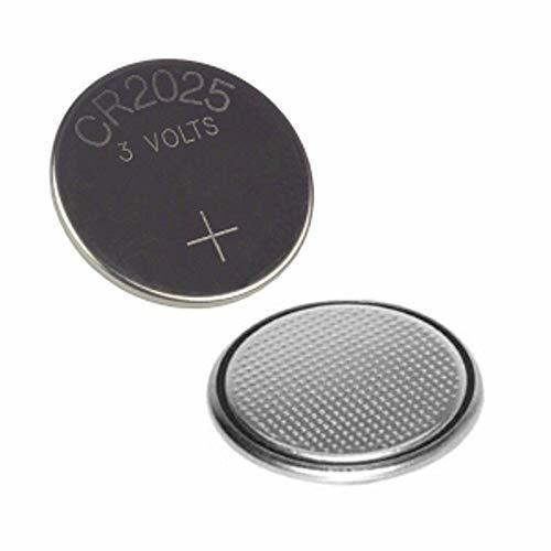
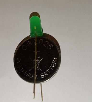
In this section, let’s understand how to use LEDs. Take a coin cell battery and connect the LED to the coin cell battery as shown in the picture. The battery has both positive and negative sides. The positive terminal is clearly marked on the battery. E.g. in the coin cell battery + sign indicates positive while the other side is negative.
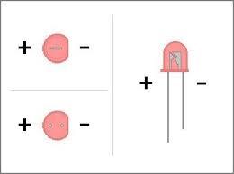
LED has two terminals, the anode (long terminal) and cathode (short terminal). LEDs come with unequal terminal lengths so that users can recognize the terminals easily. Please note that there are other markings on LED in the case leads are cut for use.
Connect the longer terminals of the LED towards the +ve side of the coin cell battery for the LED to glow with a coin cell battery, as shown in the picture.
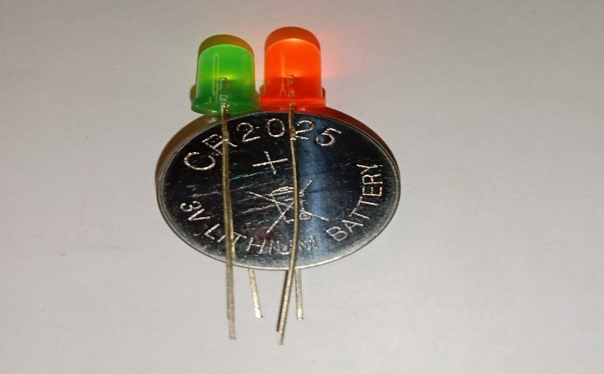
If you reverse, either battery or LEDs, the light will not glow. This is because current flows from the anode to the cathode and never in the opposite direction. This is called forward biasing in which anode of LED is connected to +ve of Battery and cathode terminal of LED is connected to the -ve terminal of the battery. A reversed LED can keep the entire circuit from operating properly by blocking current flow.
Here’s what we have learned from the above activity we know that:
Note: A light-emitting diode (LED) is a semiconductor light source that emits light when current flows through it.
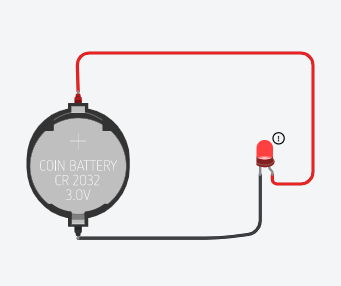
Now let’s see how can we try the above circuit on Tinkercad.
In electronics, the circuits are represented by a circuit diagram that includes a circuit symbol of the components and lines to represent the wires.
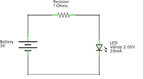
In the circuit diagram above, the battery is 3V and the LED can withstand 20mA current. To protect the LED from overcurrent we can use a resistor, which can resist the flow of current and hence protect the LED.
But how to calculate the value of the resistor. You can use the Ohm’s Law Calculators
or simply use Ohm’s Law for this calculation.
As per Ohm’s Law;
V= IR
where V= Voltage of the circuit, I = Current , R = Resistance
R=V/I
R= 3/0.02 = 150 Ohms
where: 20mA= 0.02A;
This simply means that if you add the resistor continuously with LED, which we did not in the activity above, the life of the LED may reduce.
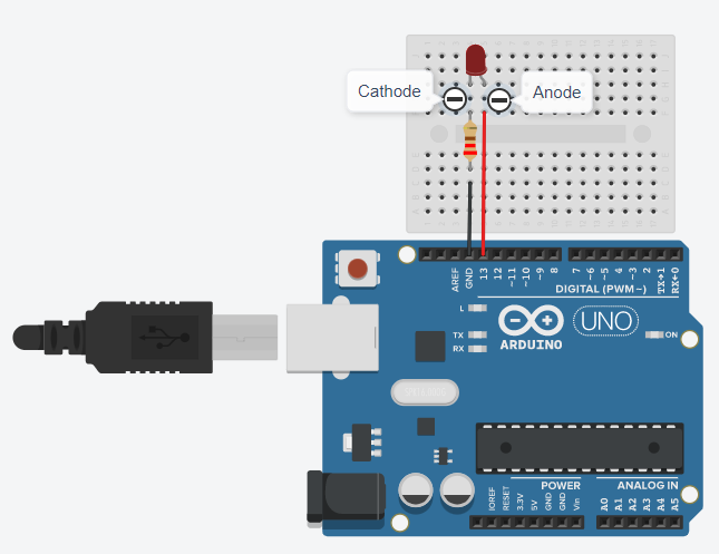
Create the below connections and follow the instructions to see the LED flashing.
Open Arduino IDE and select the options to open the blink code.

This code will make your LED flash.

To change the color of light, replace the LED with a different color LED. Green, Yellow, Blue, and white colors are the most commonly available LEDs. It is possible to get various colors on a single LED with RGB LED.
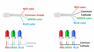
RGB LED stands for RED, GREEN, and BLUE LED. RGB LED is a combination of three LEDs in a single package that can produce almost any color.
RGB LEDs can produce 3 primary colors separately and by controlling the intensity of each of the individual LEDs you can mix and create any color you want.
RGB LEDs come with four pins, a pin for each primary color, and a common pin that can be either a common anode or a common cathode. That means RGB LEDs are 4 pin LEDs with two different packagings:
In common anode RGB all three LEDs share a common anode while in common cathode RGB the three LEDs share a common cathode.
Common anode vs common cathode LEDs
Working with RGB LEDs
Before using RGB LED it is important to test the type of RGB. This is because the connection of common anode and common cathode RGB LEDs are different on Arduino and in any circuit.
RGB LED Pins
RGB LEDs have four leads, one for each LED and another for the common anode or cathode. You can identify each lead by its length, as shown in the following figure:
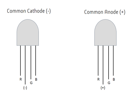
Keep the leads in the red, anode or cathode, green and blue order ensuring that the LED is facing you is such a way that the anode or cathode (the longest lead) is second from the left
Distinguishing Between RGB LED Common Anode and Common Cathode
To distinguish between a common cathode and common anode, RGB LEDs multimeter test method is most popular. Set the multimeter on continuity mode or diode mode.
On the other hand, if you have a common cathode RGB LED, you need to place the black tip of the multimeter on the longest terminal, and the red tip on one of the color terminals.
In this example, we will show you how to control the color of an RGB LED using an Arduino
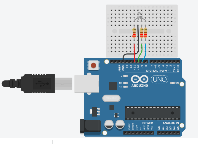
In the common cathode, RGB LED, the cathode of all the LED’s is common and common pin is connected to ground (GND) pin of Arduino and anodes (RGB terminals) of RGB LED are connected to PWM pin of Arduino board.
Note: Common pin of RGB LED is the longest pin and that is the cathode in the following picture.
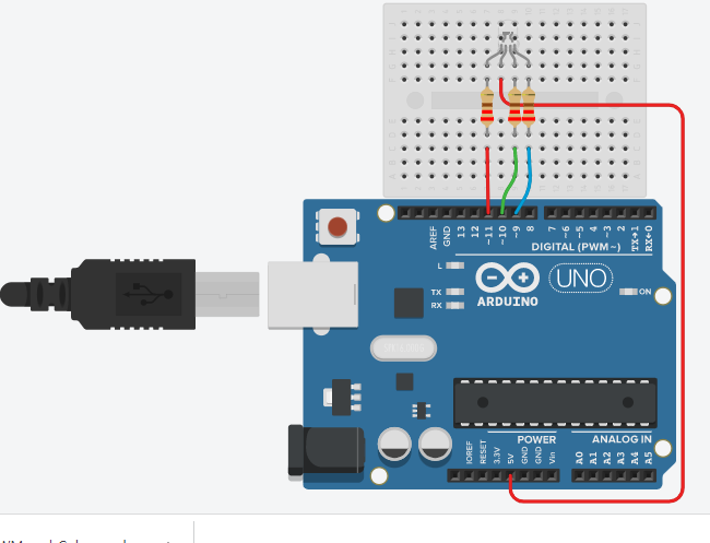
While in the common anode RGB LED, the anode of all the LEDs are common, which is connected to +5V pin of the Arduino board and cathodes(RGB terminals) of RGB LED are connected to PWM pin of Arduino board.
Note: Common pin of RGB LED is the longest pin and that is anode in the following picture.
Generate primary color on common cathode RGB LED
With an RGB LED you can produce red, green, blue light, and by configuring the intensity of each LED, you can produce other colors as well. For example, to produce red light, you’d set the red LED to the highest intensity and the green and blue LEDs to the lowest intensity.
Code to create RED color on common cathode RGB LED
int redPin= 11;
int greenPin = 10;
int bluePin = 9;
void setup() {
pinMode(redPin, OUTPUT);
pinMode(greenPin, OUTPUT);
pinMode(bluePin, OUTPUT);
}
void loop() {
analogWrite(redPin, 255);
analogWrite(greenPin, 0);
analogWrite(bluePin, 0);
delay(1000);
}
Code to create RED color on common anode RGB LED
int redPin= 11;
int greenPin = 10;
int bluePin = 9;
void setup() {
pinMode(redPin, OUTPUT);
pinMode(greenPin, OUTPUT);
pinMode(bluePin, OUTPUT);
}
void loop() {
analogWrite(redPin, 0);
analogWrite(greenPin, 255);
analogWrite(bluePin, 255);
delay(1000);
}
In additive mixing, red, green, and blue are the primary colors. The color receptors of the human eye are the most sensitive to primary colors. Primary colors are ones that cannot be created by mixing any other colors. However, all other colors can be generated by mixing primary colors in different proportions. The largest array visible to the human eye is generated by mixing primary colors with each other with full intensity of the present color.

In the last example, by turning the red, green, and blue pins ON or OFF with different combinations, basic primary and secondary colors were created.
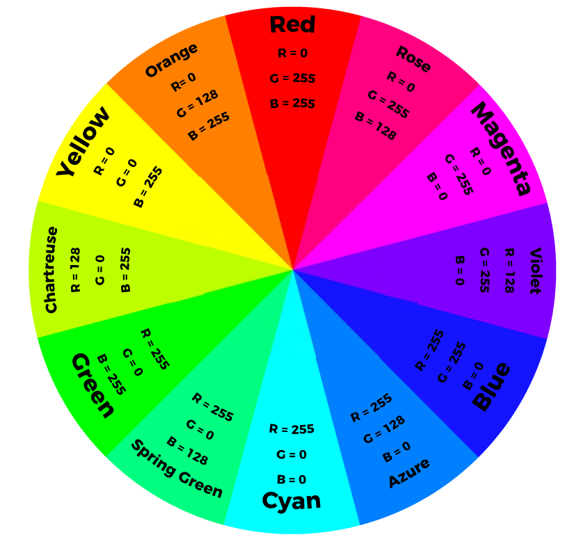
In the following example, combining the three colors at 50% brightness levels to generate tertiary colors on RGB is given. A set of 12 tertiary colors is covered in this example. Millions of color combinations can be achieved using RGB LEDs by adjusting the brightness or saturation.
To adjust the intensity of each LED, you can use a PWM (Pulse Width Modulation) by changing the percent of the time that a LED pin is on, it can create the appearance of a range of brightnesses. This percentage is called a duty cycle in which 0 percent is always OFF and 100 percent is always ON.
Before writing the code, take a look at the following color wheel to have an idea on how to combine the colors. This is a simple color mixing picture but gives you an idea on how it works and how to produce colors. These wheel PWM values will create respective colors on common cathode LEDs only. Combining the three color lights in different intensities generates different colors. This is because our eyes can see the results of the color combination, due to the proximity of the LEDs, rather than the three colors individually.
int redPin= 11;
int greenPin = 10;
int bluePin = 9;
void setup() {
pinMode(redPin, OUTPUT);
pinMode(greenPin, OUTPUT);
pinMode(bluePin, OUTPUT);
}
void loop() {
//Rose
analogWrite(redPin, 255);
analogWrite(greenPin, 0);
analogWrite(bluePin, 128);
delay(2000);
//Magenta
analogWrite(redPin, 255);
analogWrite(greenPin, 0);
analogWrite(bluePin, 128);
delay(2000);
//violet
analogWrite(redPin, 128);
analogWrite(greenPin, 0);
analogWrite(bluePin, 255);
delay(2000);
//Azure
analogWrite(redPin, 0);
analogWrite(greenPin, 128);
analogWrite(bluePin, 255);
delay(2000);
//Azure
analogWrite(redPin, 0);
analogWrite(greenPin, 128);
analogWrite(bluePin, 255);
delay(2000);
}
Code to Generate Colors on Common Anode RGB LED:
int redPin= 11;
int greenPin = 10;
int bluePin = 9;
void setup() {
pinMode(redPin, OUTPUT);
pinMode(greenPin, OUTPUT);
pinMode(bluePin, OUTPUT);
}
void loop() {
//Rose
analogWrite(redPin, 0);
analogWrite(greenPin, 255);
analogWrite(bluePin, 128);
delay(2000);
//Magenta
analogWrite(redPin, 0);
analogWrite(greenPin, 255);
analogWrite(bluePin, 0);
delay(2000);
//violet
analogWrite(redPin, 128);
analogWrite(greenPin, 255);
analogWrite(bluePin, 0);
delay(2000);
//Azure
analogWrite(redPin, 255);
analogWrite(greenPin, 128);
analogWrite(bluePin, 0);
delay(2000);
//Azure
analogWrite(redPin, 255);
analogWrite(greenPin, 128);
analogWrite(bluePin, 0);
delay(2000);
}

I have more than 12 years of experience teaching school students STEM subjects, electronic circuits, designing and prototyping in school & online. I also worked as a lead content developer with previous organizations. I like hiking and farming.
