A lot of children prefer playing videogames, instead of picking up a new skill in their free time. Moonshot Jr. has developed The MOONUINO 5×5 LED Matrix Shield which has introduced a fun and gamified way of learning for children. Using this shield, children of different ages will not only will not only learn to create innovative and exciting projects, but also use their creations to have fun. In this blog we will discuss how to use the LED Matrix, its key features. and the different ways it can be used.
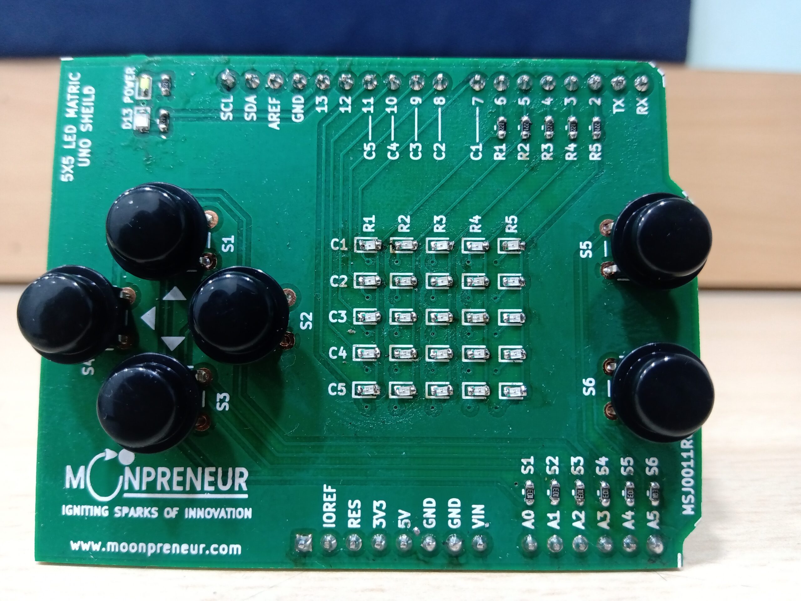
Step 1: Unpack the MOONUINO 5×5 LED Matrix Shield.
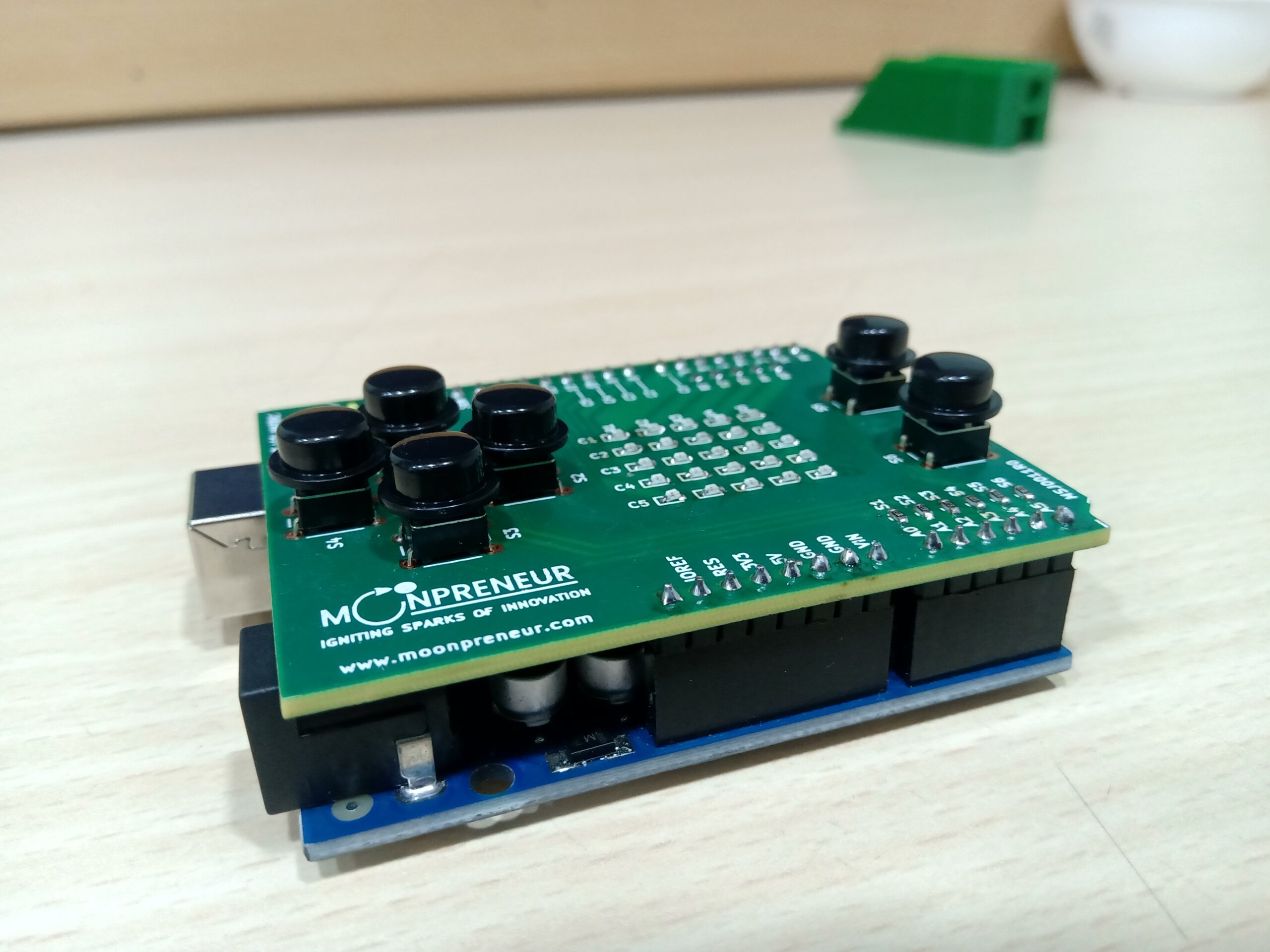
Step 2: Plug the Interfacing pins on the shield into the Arduino Uno Board, such that the shield rests on top of the board.
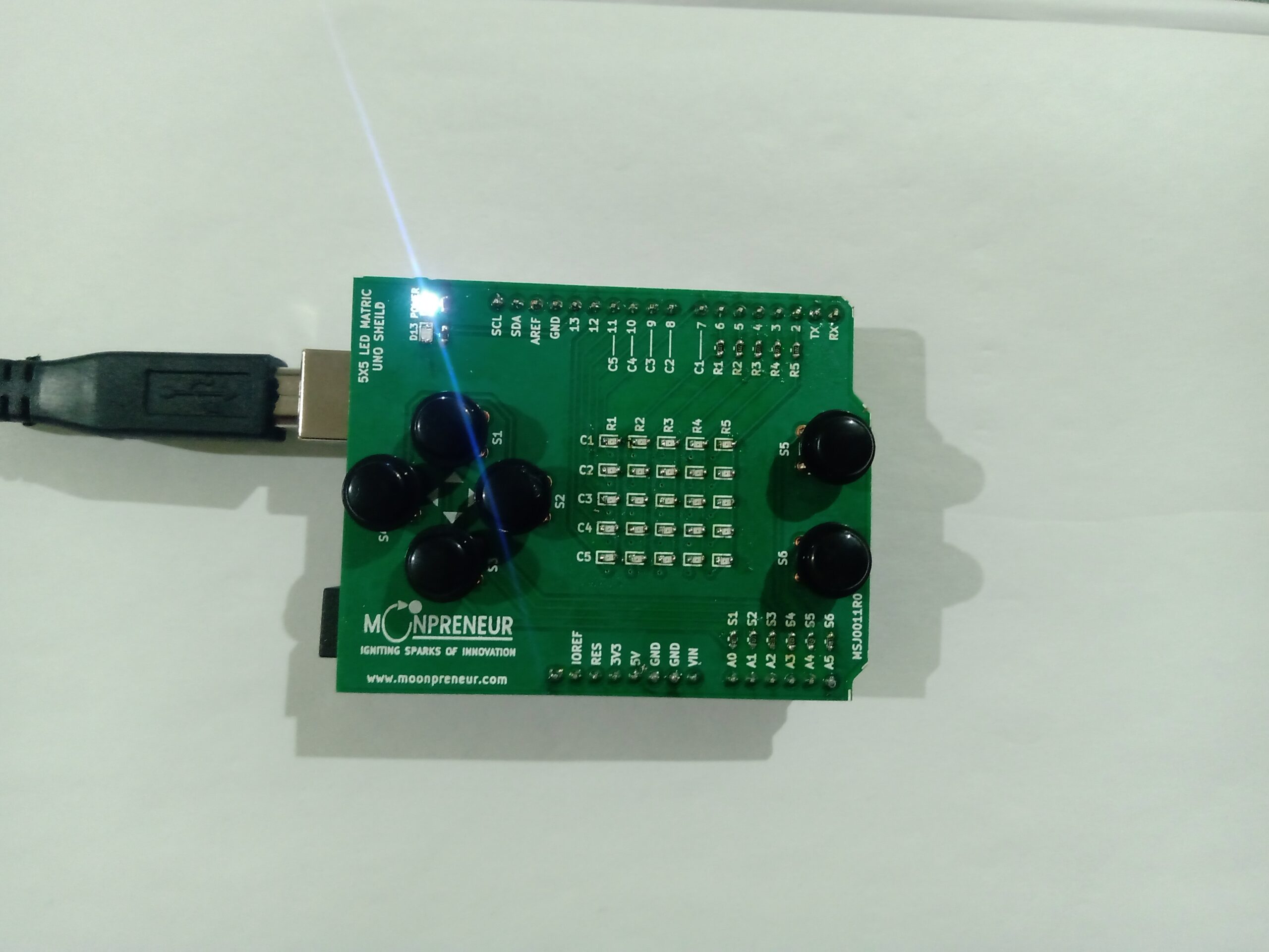
Step 3: Connect the Shield and Arduino Uno Board combination to a laptop for power supply using a USB cable.
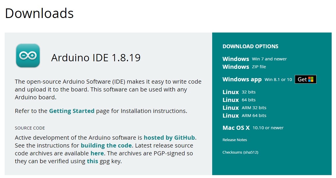
Step 4: Visit https://www.arduino.cc/en/software and download the Arduino IDE on your computer
Step 5: Copy the code responsible for the functionality of the Matrix Shield, and paste the code in the IDE.
// 2-dimensional array of row pin numbers:
int ROW[] = {6,5,4,3,2};
// 2-dimensional array of column pin numbers:
int COL[] = {11,10,9,8,7};
int s1, s2, s3, s4, s5, s6;

unsigned char UP[5][5]=
{
  0,0,1,0,0,
  0,0,0,1,0,
  1,1,1,1,1,
  0,0,0,1,0,
  0,0,1,0,0,
};

unsigned char DOWN[5][5]=
{
  0,0,1,0,0,
  0,1,0,0,0,
  1,1,1,1,1,
  0,1,0,0,0,
  0,0,1,0,0,
};

unsigned char LEFT[5][5]=
{
  0,0,1,0,0,
  0,1,1,1,0,
  1,0,1,0,1,
  0,0,1,0,0,
  0,0,1,0,0,
};

unsigned char RIGHT[5][5]=
{
  0,0,1,0,0,
  0,0,1,0,0,
  1,0,1,0,1,
  0,1,1,1,0,
  0,0,1,0,0,
};

unsigned char ring1[5][5]=
{
  0,0,0,0,0,
  0,0,0,0,0,
  0,0,1,0,0,
  0,0,0,0,0,
  0,0,0,0,0,
};

unsigned char ring2[5][5]=
{
  0,0,0,0,0,
  0,1,1,1,0,
  0,1,0,1,0,
  0,1,1,1,0,
  0,0,0,0,0,
};

unsigned char ring3[5][5]=
{
  1,1,1,1,1,
  1,0,0,0,1,
  1,0,0,0,1,
  1,0,0,0,1,
  1,1,1,1,1,
};

void setup()
{
   // iterate over the pins:
   Serial.begin(115200);
   pinMode(A0, INPUT); //s1
   pinMode(A1, INPUT); //s2
   pinMode(A2, INPUT); //s3
   pinMode(A3, INPUT); //s4
   pinMode(A4, INPUT); //s5
   pinMode(A5, INPUT); //s6

   for(int i = 0;i<5;i++)
  // initialize the output pins:
  {
    pinMode(ROW[i],OUTPUT);
    pinMode(COL[i],OUTPUT);
  }
}

void loop()
{
  s1=digitalRead(A0);
  //delay(10);
  s2=digitalRead(A1);
  //delay(10);
  s3=digitalRead(A2);
  //delay(10);
  s4=digitalRead(A3);
  //delay(10);
  s5=digitalRead(A4);
  //delay(10);
  s6=digitalRead(A5);
  //delay(10);

   if(PINC & B00000001) //UP s1
  {
  for(int i = 0 ; i < 80  ; i++)
  {
    Display(UP);
    }
     //delay(1);
}

if(PINC & B00000010) //RIGHT s2
  {
    Serial.println("--s2--");
  for(int i = 0 ; i < 80  ; i++)
  {
    Display(RIGHT);
    }
     //delay(1);
}

  if(PINC & B00000100) //DOWN s3
  {
  for(int i = 0 ; i < 80  ; i++)
  {
    Display(DOWN);
    }
    //delay(1);
  }

  if(PINC & B00001000) //LEFT s4
  {
  for(int i = 0 ; i < 80  ; i++)
  {
    Display(LEFT);
    }
     //delay(1);
  }

 if(PINC & B00010000) //s5 rings expanding
  {
    for(int i = 0 ; i < 60  ; i++){
    Display(ring1);
    //delay(1);
    }
    for(int i = 0 ; i < 60  ; i++){
    Display(ring2);
    //delay(1);
    }
    for(int i = 0 ; i < 60  ; i++){
    Display(ring3);
    //delay(1);
    }
  }

  if(PINC & B00100000) //s6 rings shrinking
  {
    for(int i = 0 ; i < 60  ; i++){
    Display(ring3);
    }

    for(int i = 0 ; i < 60  ; i++){
    Display(ring2);
    }

    for(int i = 0 ; i < 60  ; i++){
    Display(ring1);
    }
  }
}

void Display(unsigned char  dat[5][5])
{
  for(int c = 0; c<5;c++)
  {
    digitalWrite(COL[c],LOW);//use the column
    for(int r = 0;r<5;r++)
    {
      digitalWrite(ROW[r],dat[r][c]);
    }
    delay(1);
    Clear();  //Remove empty display light
  }
}

void Clear()
{
  for(int i = 0;i<5;i++)
  {
    digitalWrite(ROW[i],LOW);
    digitalWrite(COL[i],HIGH);
  }
}
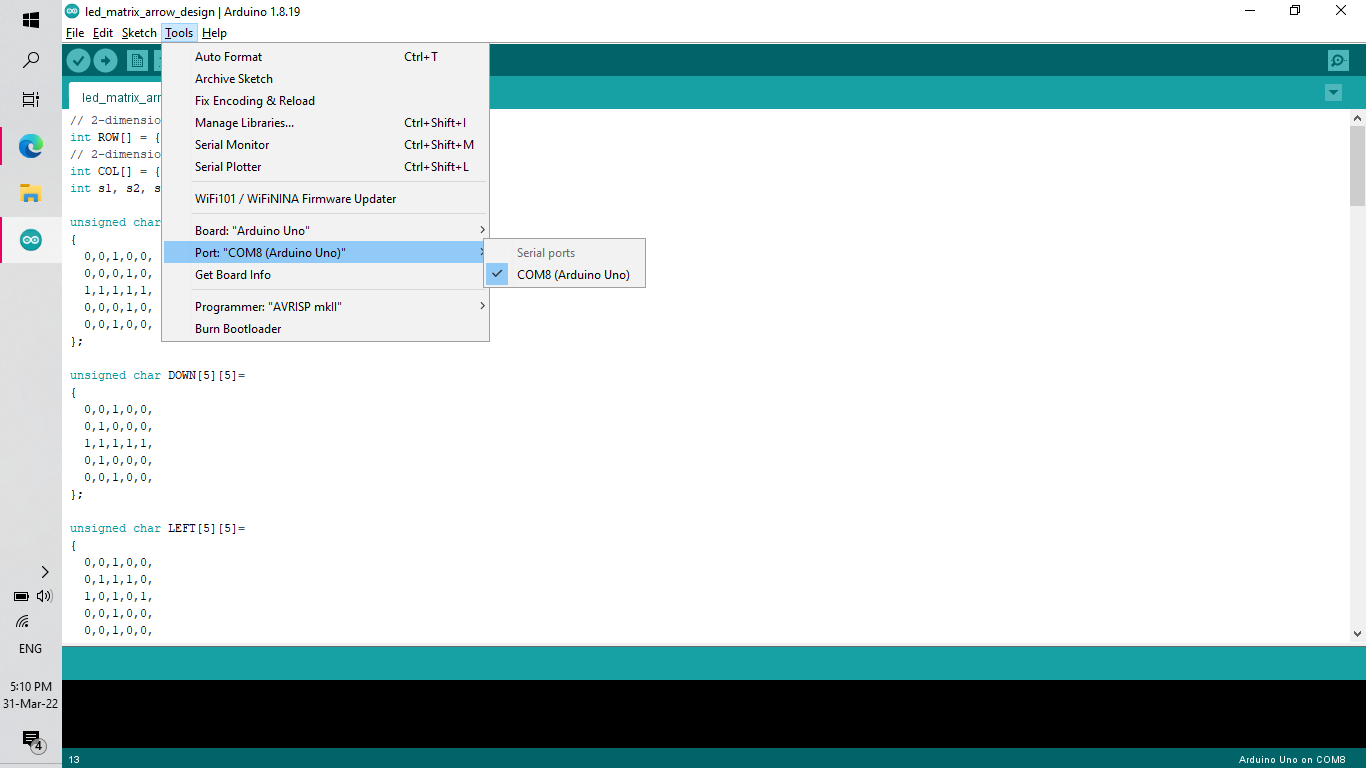
Step 6: Open the editor and configure your IDE according your board in the tools section.
Step 7: Upload the code on the board, by clicking on the button highlighted in yellow.

Step 8: Play around with your completed project.
The Use cases of the 5×5 LED Matrix Shield is only limited to the extent of your creativity. Some of the projects you can make with this shield are:

