
The Moonpreneur Traffic Light kit will help you understand how traffic lights work in a fun and creative way. Let us get our hands on this kit and understand how it works. We are going to have lots of fun working and learning on the traffic light kit today.
The Moonpreneur Traffic Light kit will help you understand how traffic lights work in a fun and creative way, let us get our hands on this kit and understand how it works. We are going to have lots of fun working and learning on the traffic light kit today.
Here is the list of items you will find as soon as you unpack the kit.
Controller Board – TL001

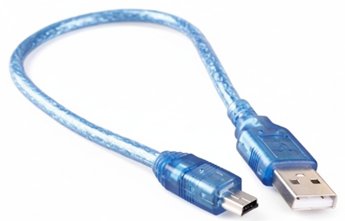
USB Cable – TL002
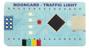
Mooncard – TL003
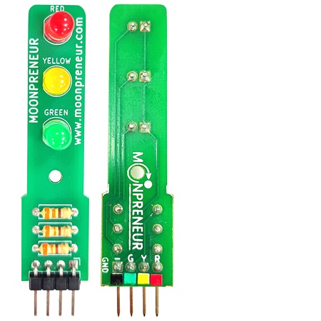
Traffic Light Board – TL004
Connection Wires – TL005

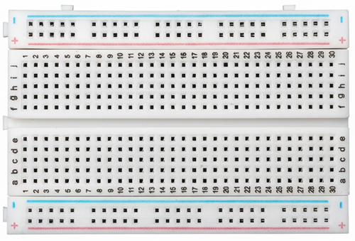
Breadboard – TL006
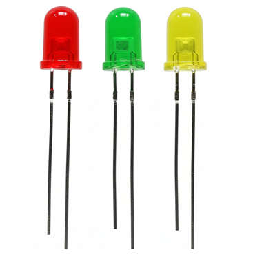
LEDs (2 of each color) – TL007
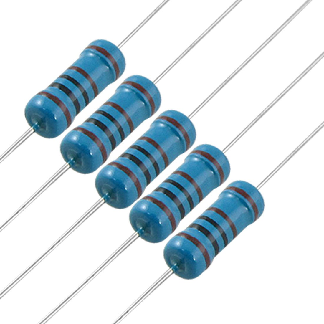
Resistors – TL008
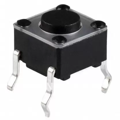
Push Button – TL009
Follow these steps if you have received the Mooncard (TL003) inside the Traffic Light Kit.
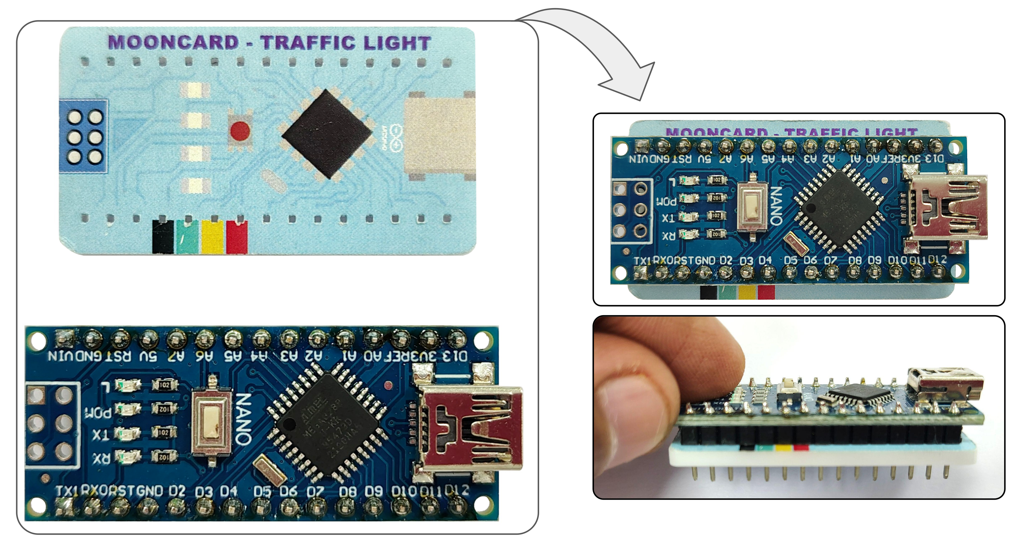
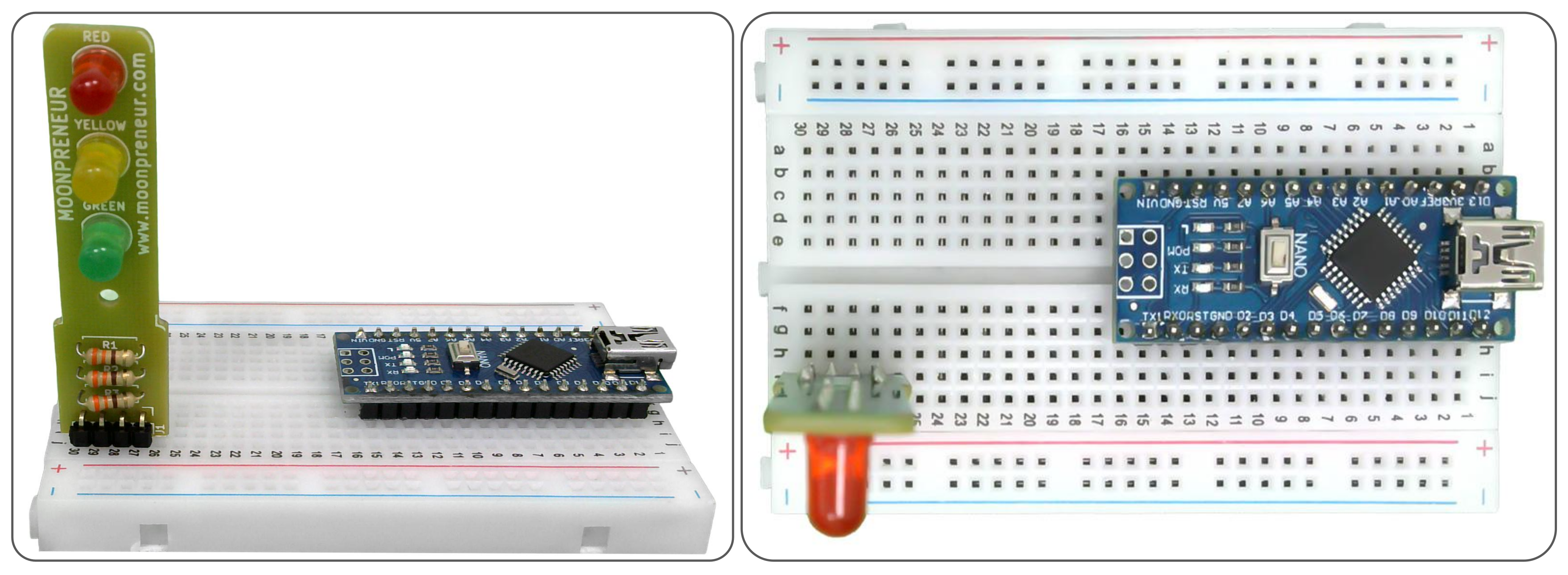
Step 1: Open the kit and you should be able to find the Controller board (TL001 – It is an Arduino Nano Compatible Board) and the Mooncard – (TL003).
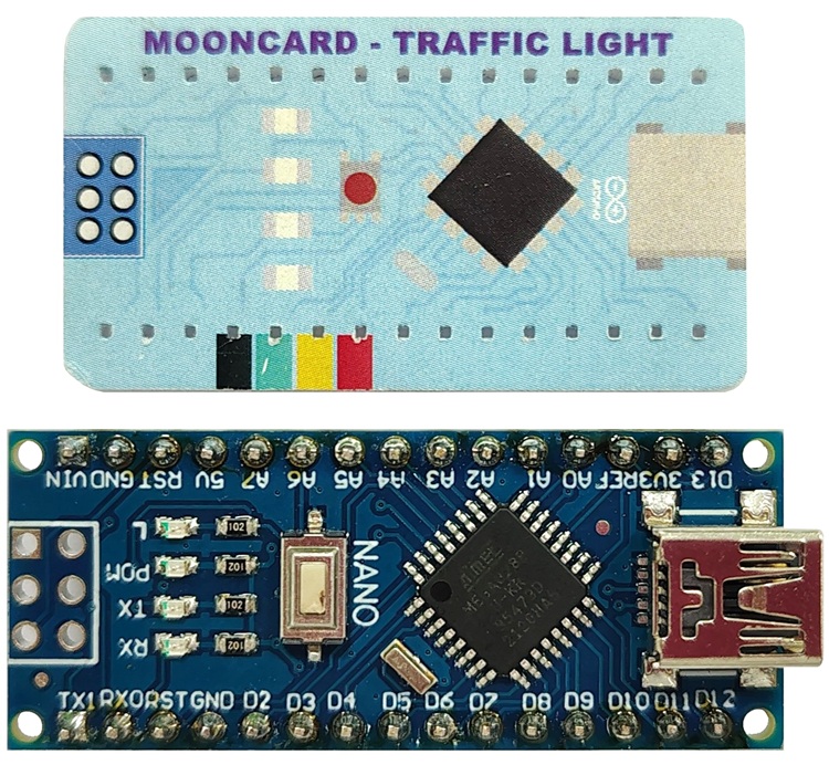
Step 2: Insert the Controller Board (TL001) in the Mooncard (TL003) as indicated. Match the drawing in the Mooncard, aligning the connectors and pins, otherwise it will not work
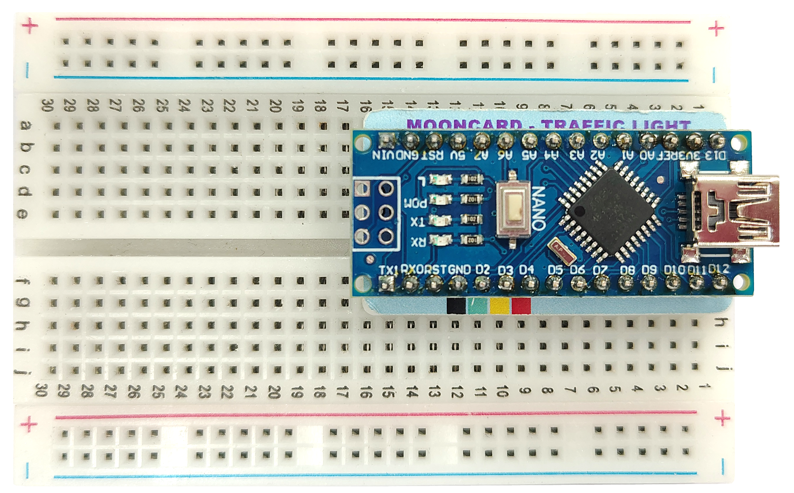
Step 3 : Insert the combination of the Controller Board (TL001) and Mooncard (TL003) in the Breadboard (TL006) as indicated. Ensure that the controller board’s connector is at the edge of the breadboard and the pins are aligning as per the diagram.
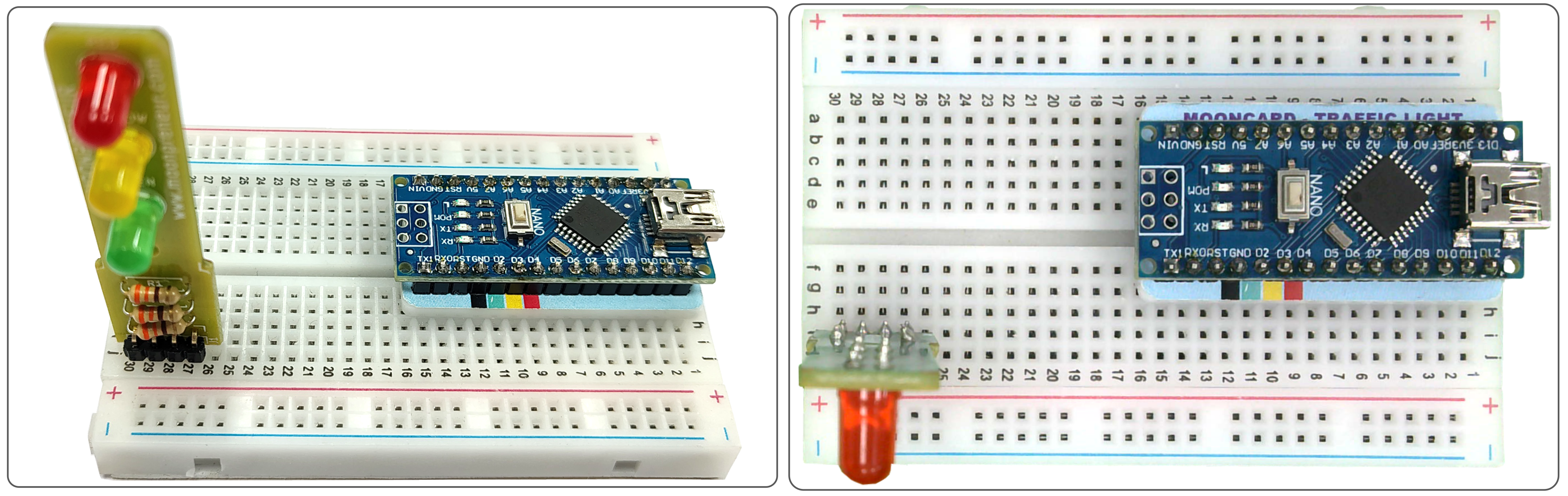
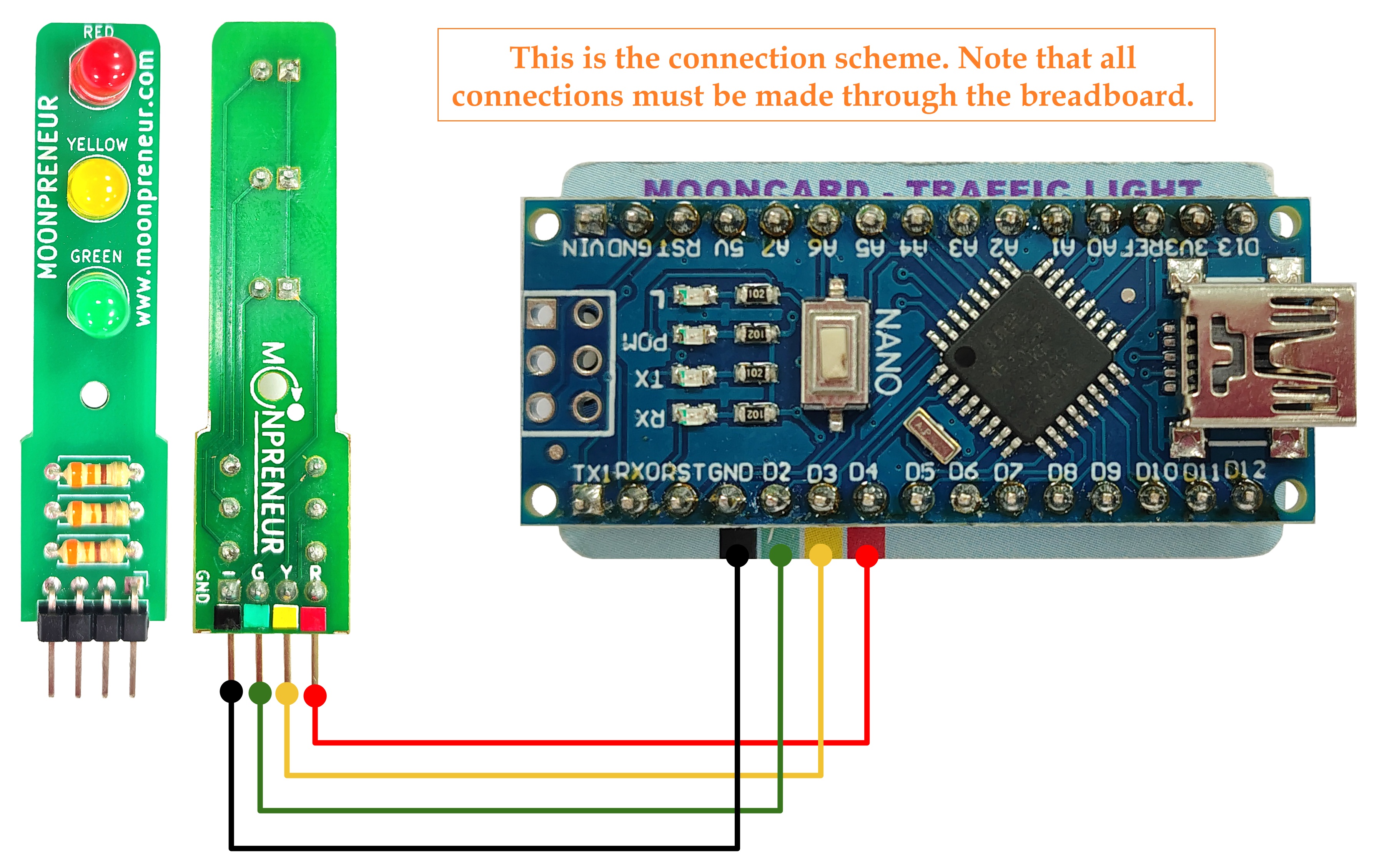
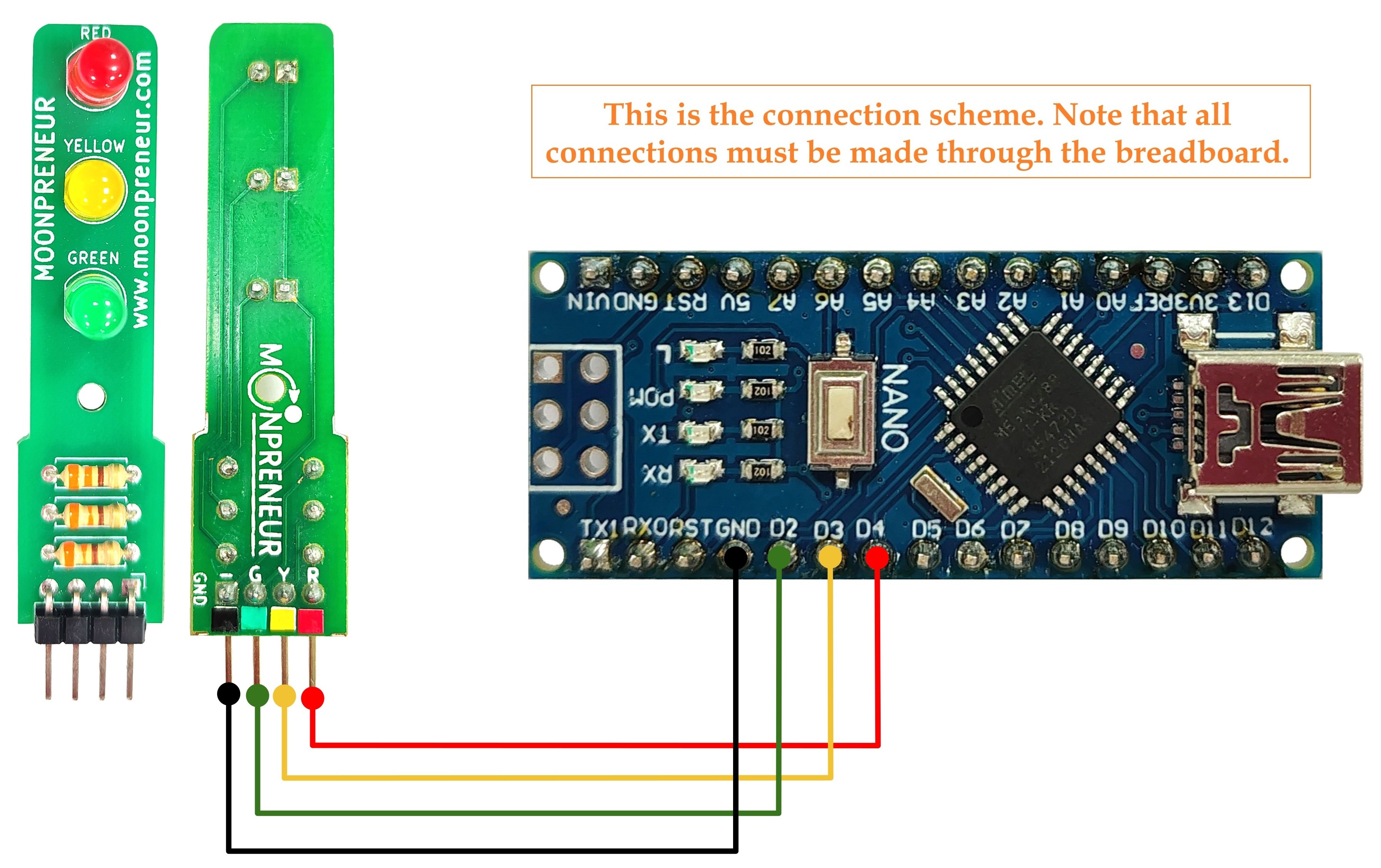
Step 4 : Find the Traffic Light Board (TL004) in the kit, it has 4 colored pins at one end. In the next step we will be connecting the 4 pins with the controller board using the provided wires
Step 5: Insert the Traffic Light Board (TL004) in the breadboard, as indicated.
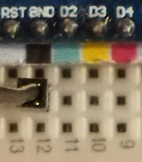
Step 6: Use a black (or any other color) wire and insert one end to an empty hole in the breadboard in front of the black mark on the controller board.
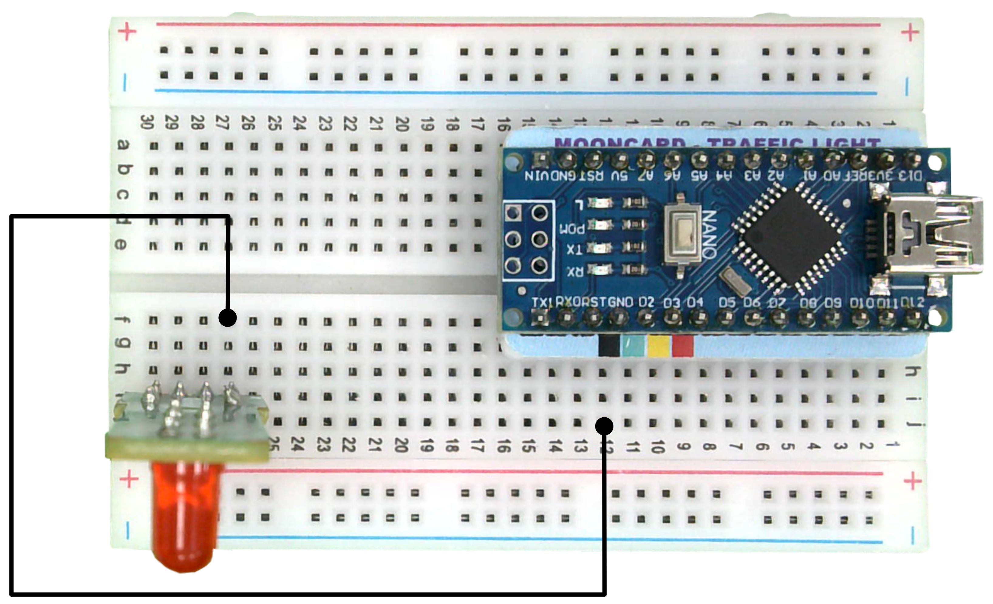
Insert the other end of the wire in the empty hole on the breadboard in front of the traffic light board’s black pin.
Make sure the end of the wire is inserted in front of the black color of the controller board.
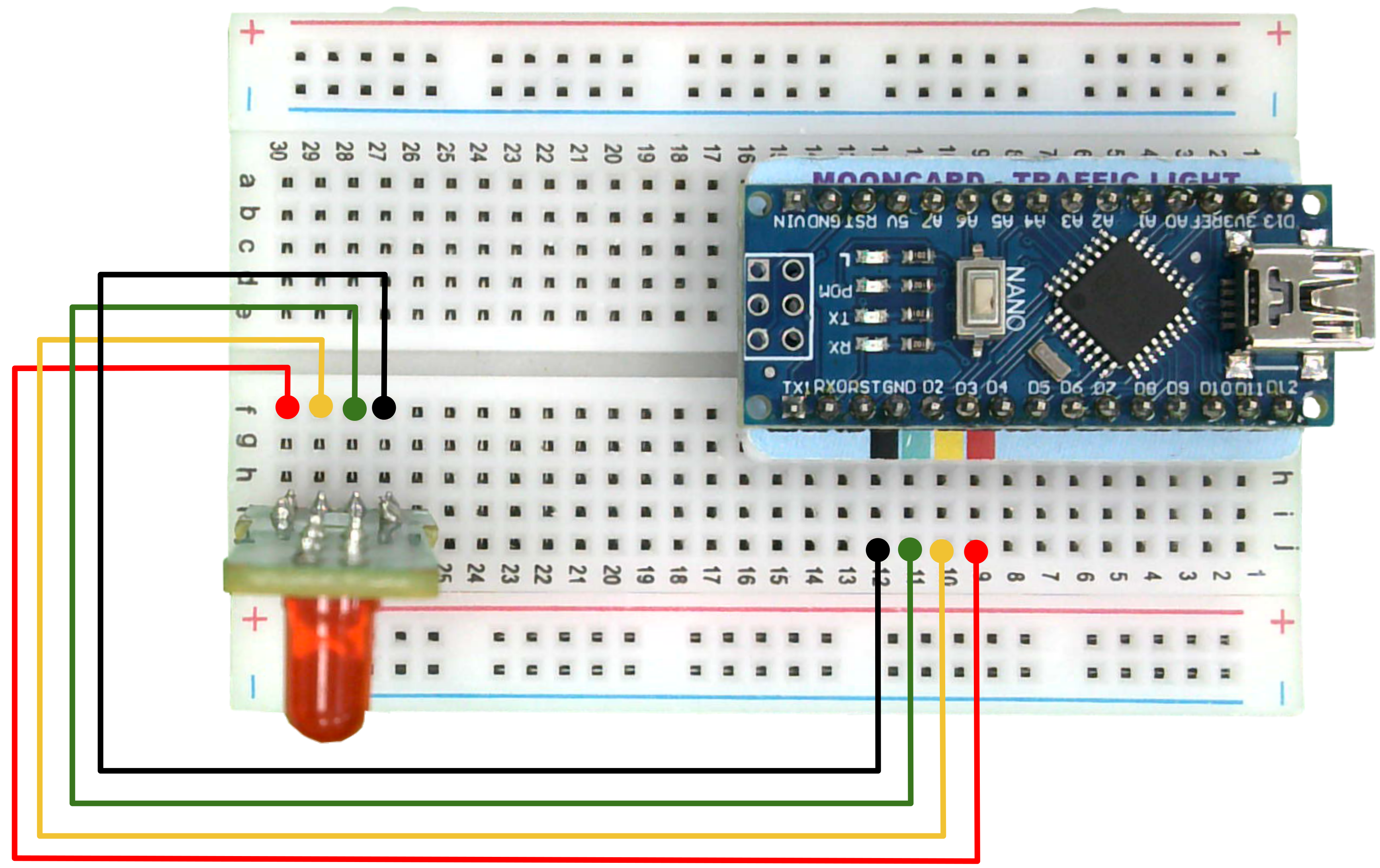
Step 7: Repeat the previous process for the remaining pins.
| Wire | Traffic Board | Controller Board |
| Red | Red | Red (D4) |
| Yellow | Yellow | Yellow (D3) |
| Green | Green | Green (D2) |
| Black | Black | Black (GND) |
Follow these steps if you haven’t received the Mooncard (TL003) ![]() inside the Traffic Light Kit.
inside the Traffic Light Kit.
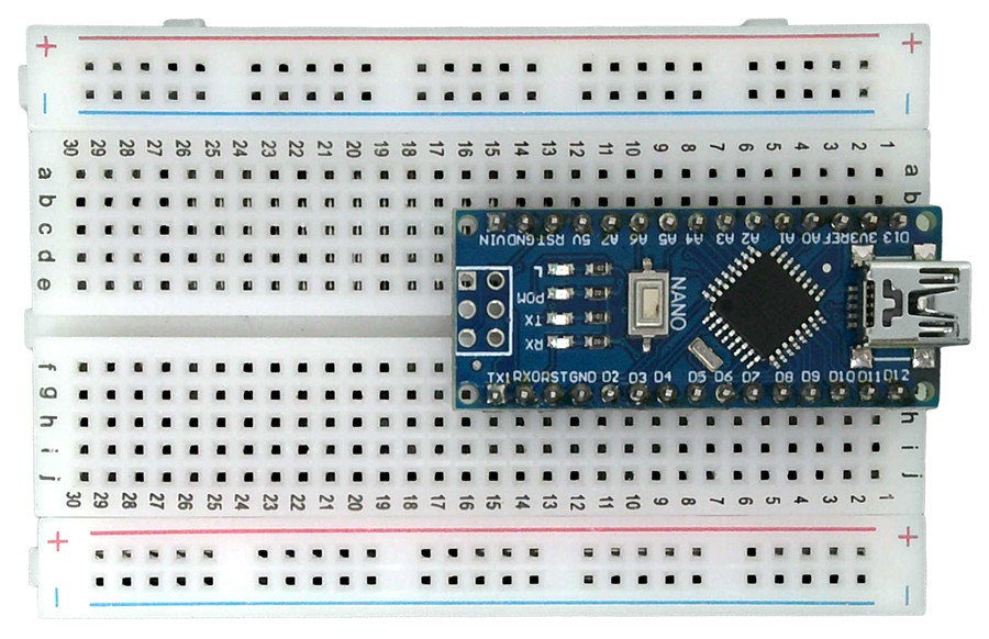
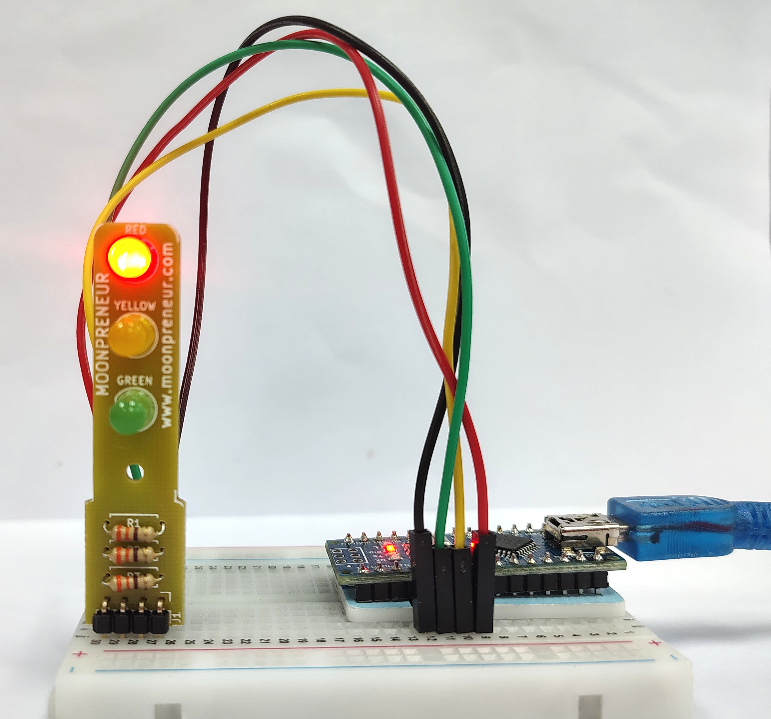
Step 1 : Insert the Controller Board (TL001) in the Breadboard (TL006). Ensure that the USB connector is at the edge of the Breadboard and the pins are aligning, as shown in the image below.
Step 2 : Insert the Controller Board (TL001) and Traffic Light Board (TL004) in the Breadboard (TL006). Ensure that the USB connector is at the edge of the Breadboard and the pins are aligning, as shown in the image below.
Step 3 : Use a black (or any other color) wire and insert one end to an empty hole in the breadboard in front of the GND pin of the controller board.
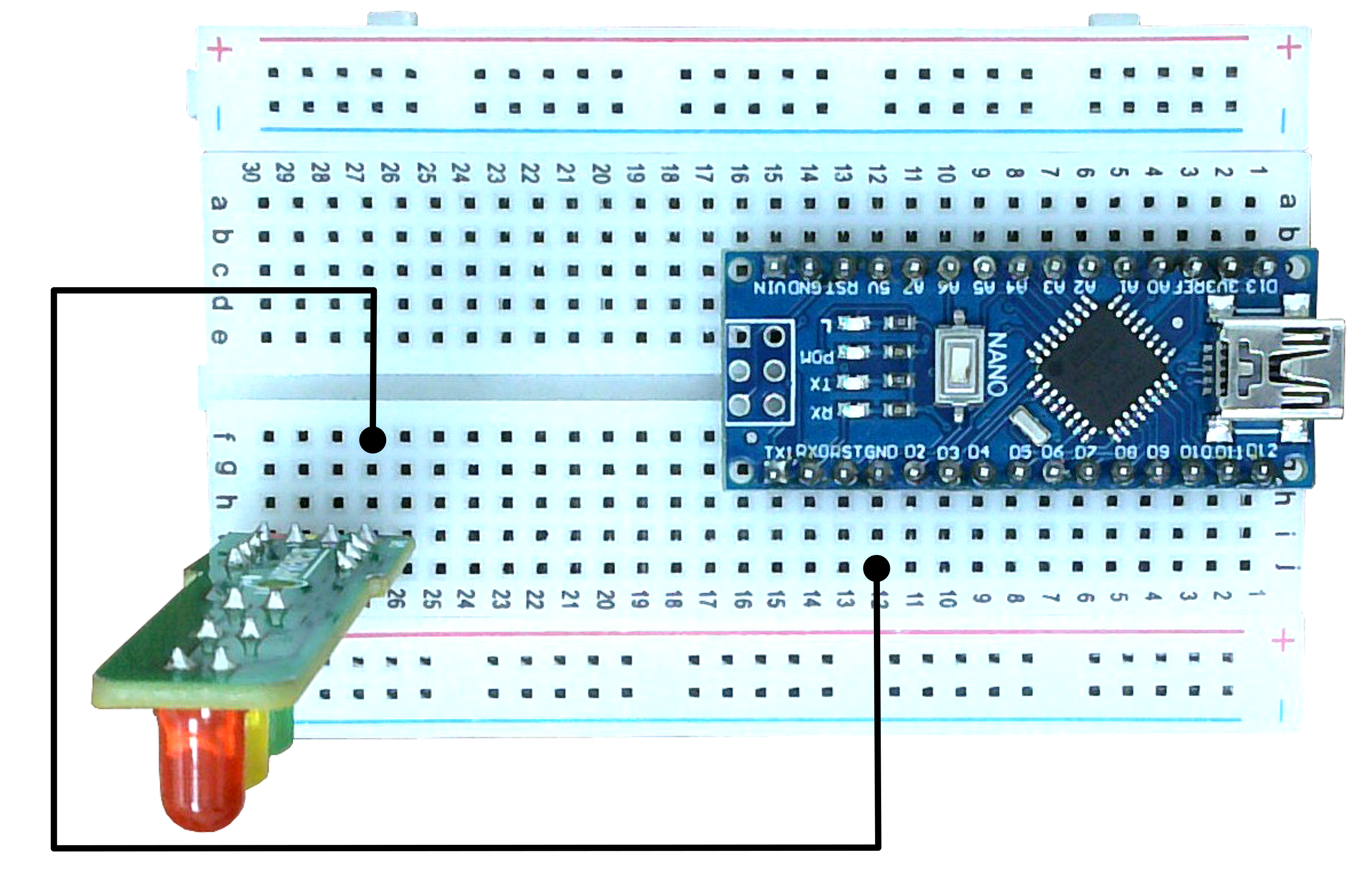
Insert the other end of the wire in the empty hole on the breadboard in front of the traffic light board’s GND (-) pin.
Note: Make sure the end of the wire is inserted in front of the GND pin of the controller board.
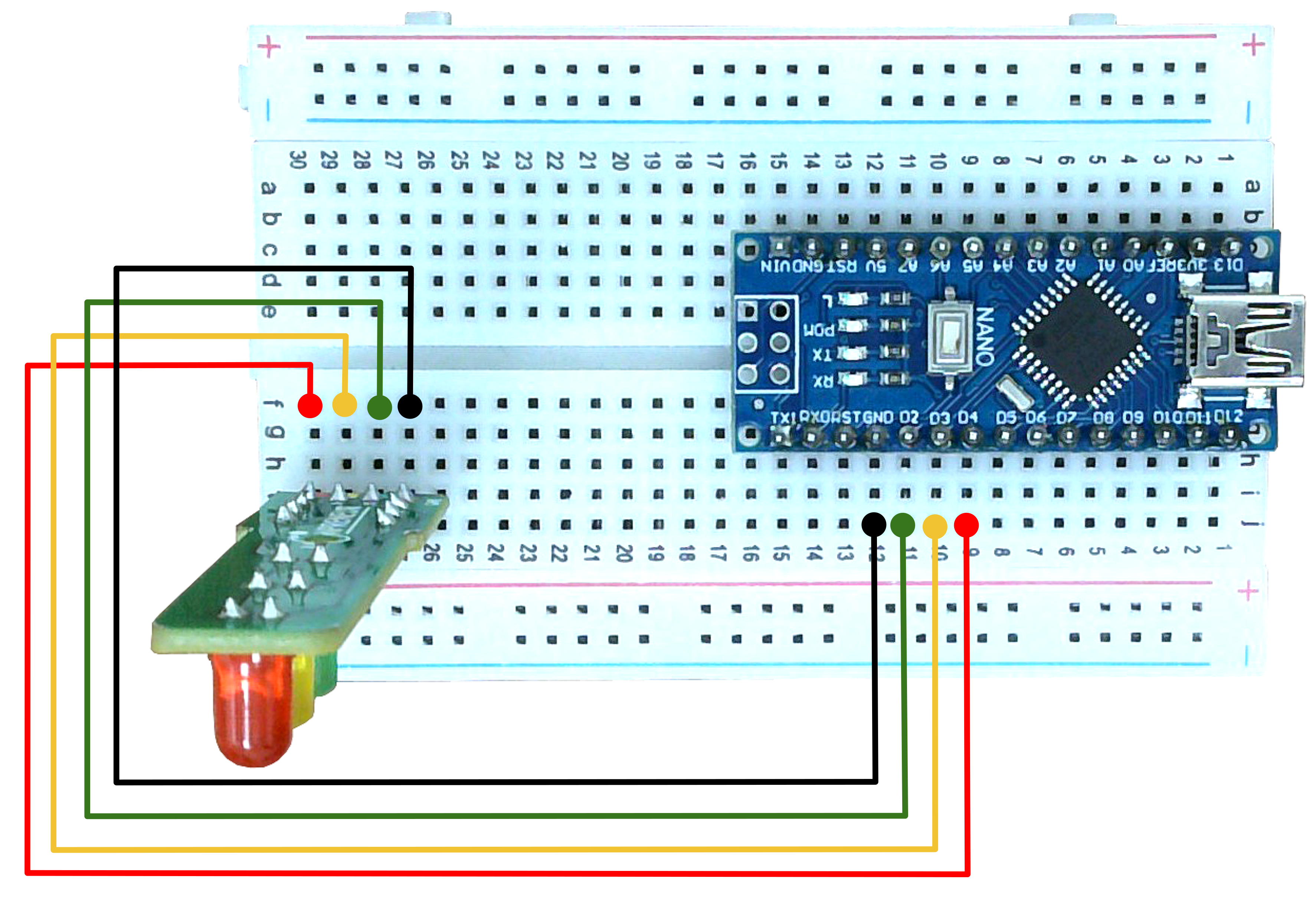
Step 4 : Repeat the previous process for the remaining pins.
| Wire | Traffic Board | Controller Board |
| Red | Red | D4 |
| Yellow | Yellow | D3 |
| Green | Green | D2 |
| Black | Black | GND |
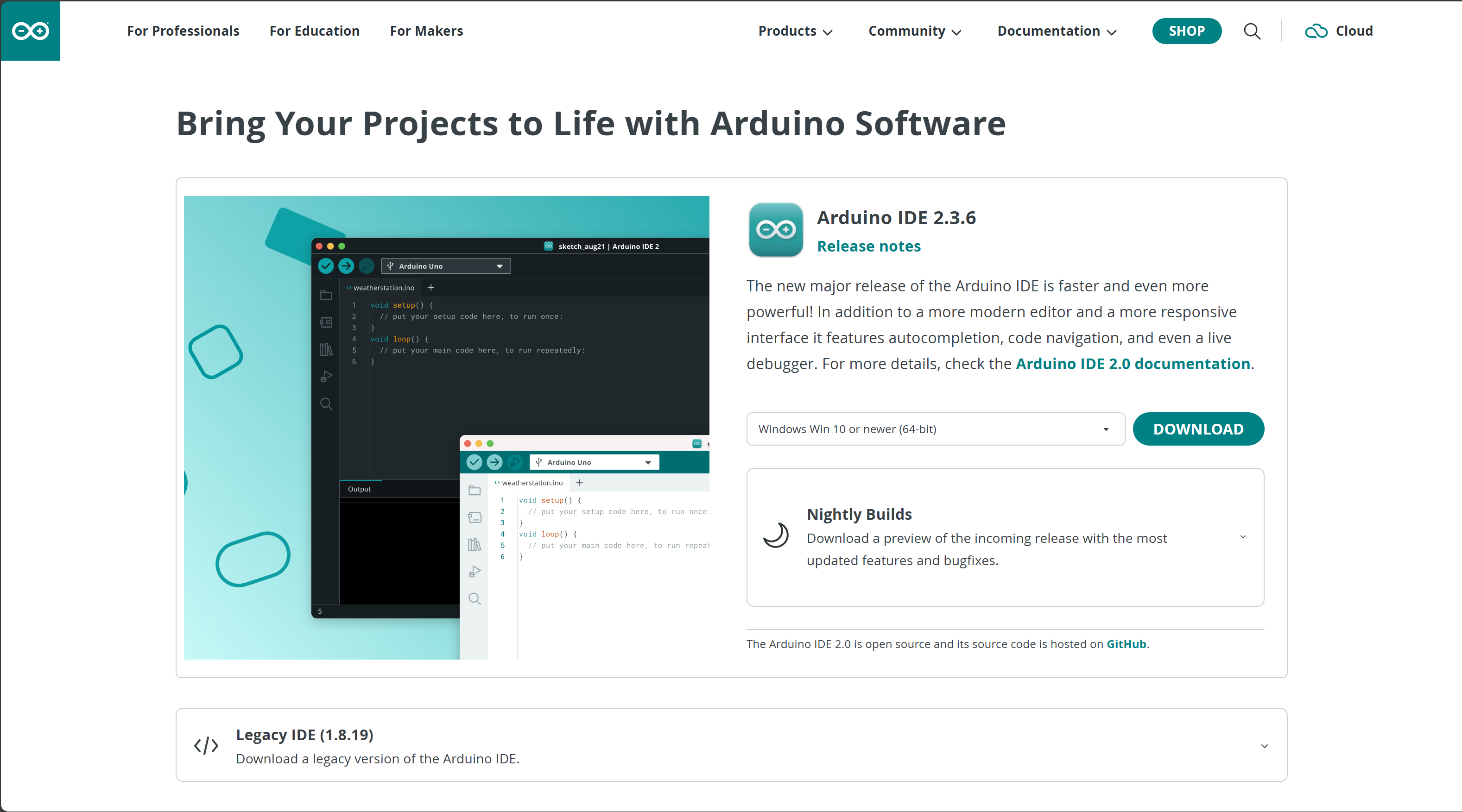
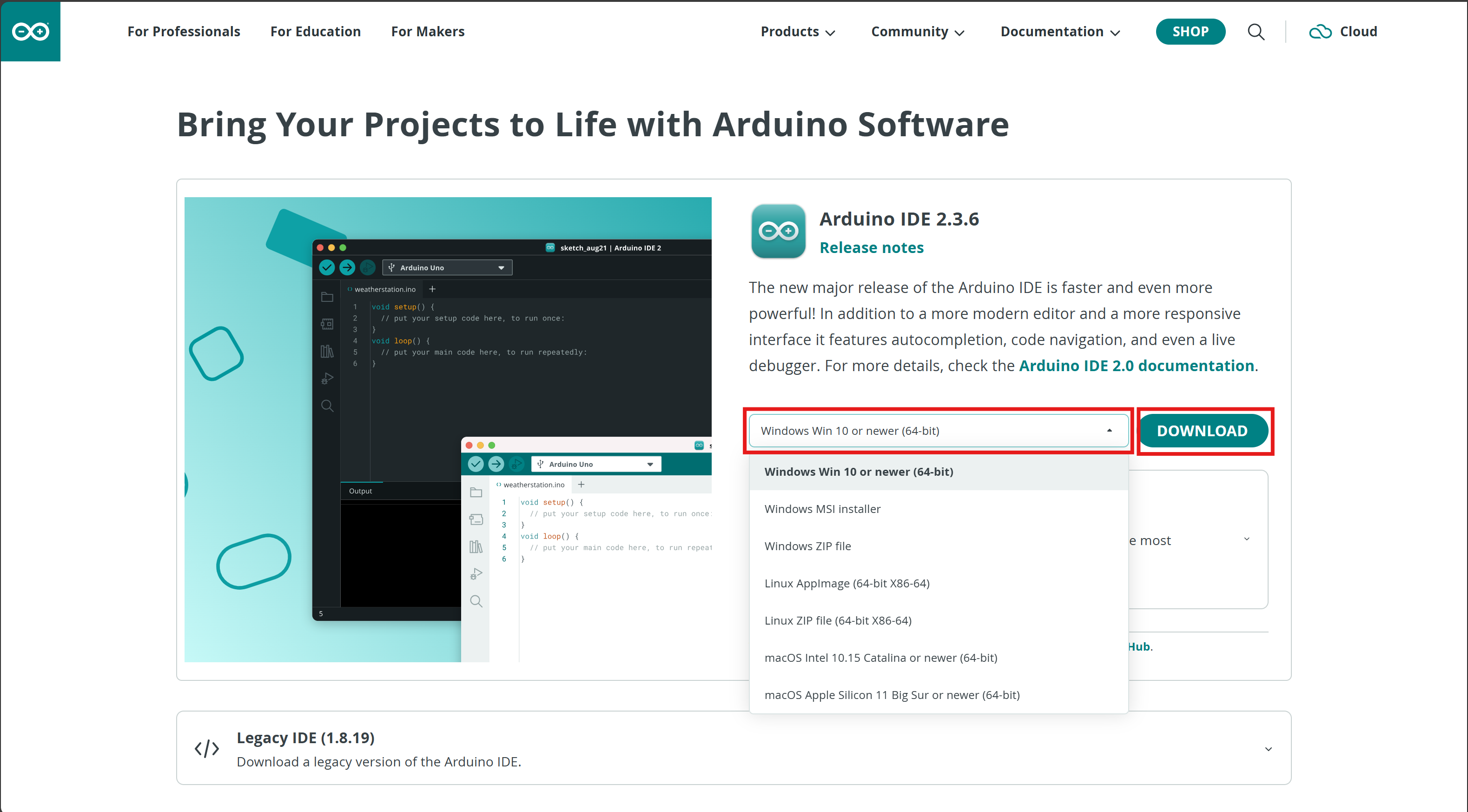
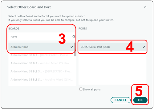
Before writing any code, you’ll need to install the Arduino IDE (Integrated Development Environment) — the software used to write, upload, and run programs on your Arduino Nano.
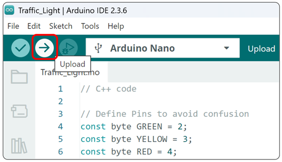
Copy the code given below.
// C++ code

// Define Pins to avoid confusion
const byte GREEN = 2;
const byte YELLOW = 3;
const byte RED = 4;

// The setup function defines the initial state of the Arduino upon boot and runs only once.
void setup()
{
  // Initialize the pins (give an initial value)
  pinMode(GREEN, OUTPUT);   // pin number 2 (Green) configured for output
  pinMode(YELLOW, OUTPUT);  // pin number 3 (Yellow) configured for output
  pinMode(RED, OUTPUT);     // pin number 4 (Red) configured for output
}

// Run code (write code that will keep on executing throughout the loop)
void loop()
/* The loop describes the main logic of your circuit,
   runs again and again as its name suggests,
   and is executed after the setup has finished executing. */
{
  digitalWrite(RED, HIGH);     // When set to HIGH, current is supplied to the pin (5V) and the LED lights up
  digitalWrite(YELLOW, LOW);   // When set to LOW, current supplied to the pin is 0V and the LED doesn't light up
  digitalWrite(GREEN, LOW);
  delay(4000);                 // 1 second = 1000 milliseconds, wait for 4 seconds

  digitalWrite(GREEN, HIGH);
  digitalWrite(RED, LOW);
  digitalWrite(YELLOW, LOW);
  delay(4000);                 // Wait for 4000 millisecond(s)

  digitalWrite(YELLOW, HIGH);
  digitalWrite(GREEN, LOW);
  digitalWrite(RED, LOW);
  delay(1500);                 // Wait for 1500 millisecond(s)
}

1. All lines that begin with // are comments. Comments are skipped while when the code is executed, they enhance the understanding of the code. Following two lines are comments, for example.
// C++ code
//Define Pins to avoid confusion
2. In the block of code below, we define the pin numbers that we are going to use with a simple name to avoid confusion and make the code easy to understand.
const byte GREEN = 2;
const byte YELLOW = 3;
const byte RED = 4;
3. In the block of code below, the setup is used to initialize or give initial values to the pins, which will decide how these pins will function throughout the execution of the code.
void setup()//The setup function defines the initial state of the Arduino upon boot and runs only once.
{
  pinMode(GREEN, OUTPUT);//pin number 8 Green) configured for output
  pinMode(YELLOW, OUTPUT);//pin number 7 (Yellow) configured for output
  pinMode(RED, OUTPUT);//pin number 2 (Red) configured for output
}
4. Inside the loop resides the code that will keep on executing endlessly. The line of code given below turns on the Red LED while turning the other LED off, it waits for 4 seconds and then turns on only the Green LED while keeping other LEDs off. It again waits for 4 seconds and turns only the Yellow LED on, waits for 1.5 seconds and then starts over with the Red LED.
void loop()
/*The loop describes the main logic of your circuit, runs again and again as its name suggests,
and is executed after the setup has finished executing.*/
{
  digitalWrite(RED, HIGH);//When Set to HIGH current is supplied to the pin (5v) and the LED lights up
  digitalWrite(YELLOW, LOW);//When Set to LOW current supplied to the pin is 0v and the LED doesn't light up
  digitalWrite(GREEN, LOW);
  delay(4000); // 1 second = 1000 milliseconds, wait for 4 seconds.
  digitalWrite(GREEN, HIGH);
  digitalWrite(RED, LOW);
  digitalWrite(YELLOW, LOW);
  delay(4000); // Wait for 4000 millisecond(s)
  digitalWrite(YELLOW, HIGH);
  digitalWrite(GREEN, LOW);
  digitalWrite(RED, LOW);
  delay(1500); // Wait for 1500 millisecond(s)
}
With the explanation given above, you can experiment with the code and make your own changes. If you wanted to change how fast traffic lights switch, you could change the value of delay.

Vikas Shukla, an innovator at heart whose undivided attention is dedicated to technology. His inquisitiveness to create has led to several innovations in the field of hardware and software. He is the architect behind several successful learning products for students. These tool kits are a part of the curriculum at Moonpreneur.
