
In robotics, one of the most fundamental requirements, and yet often under-appreciated, is the robot’s ability to know where things are in space: where the robot itself is, where its parts are, and where objects in the world are. This spatial reasoning depends critically on the idea of a coordinate frame. A coordinate frame (or reference frame) gives a consistent way to represent positions and orientations of points, bodies, sensors, tools, and the environment. Without it, a robot cannot meaningfully act, plan, or interact with its surroundings.
In this blog, we will explore what coordinate frames are, the common types used in robotics, how transformations link them, why this matters (mathematically and practically), and some of the main challenges one must be careful about.
📦 Fact Box #1 – Did You Know?
Every robot, whether a simple robotic arm or an autonomous car, uses dozens of coordinate frames at once.
These include world frames, base frames, camera frames, IMU frames, tool frames, and object frames—all connected through transformations.
What is a Coordinate Frame? Anatomy & Types
Anatomy of a Frame
A coordinate frame consists of:
- An origin, which is a defined point in space (e.g., the base of the robot, or the center of a sensor).
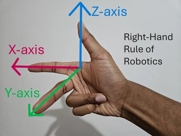
- A set of basis vectors (often denoted i,j,k or the X, Y, Z axes) that define orientation. These axes are mutually perpendicular in a 3-D Cartesian frame.
- A convention — most commonly the right-hand rule for defining the positive direction of axes (e.g., index finger → X, middle finger → Y, thumb → Z) for consistency.
Coordinates of any point become meaningful only when expressed relative to a specific frame.
Common Types of Frames in Robotics
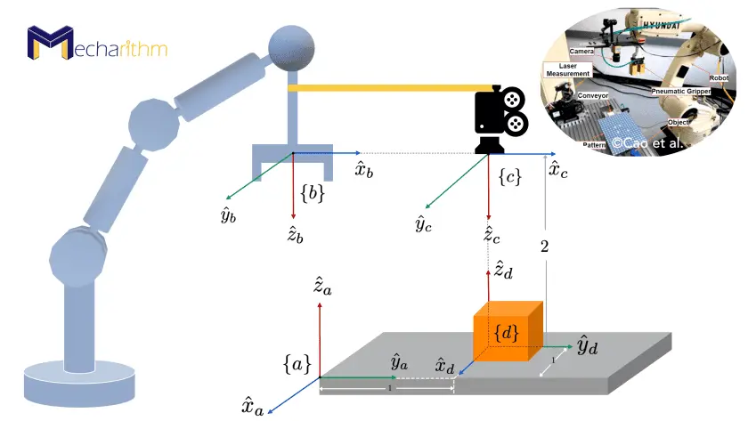
In a typical robotic system, multiple frames exist simultaneously, each serving a different purpose. Some widely used ones are:
- World (Global) Frame (W) — a fixed, global reference for the environment. For example, the floor of a factory, the lab coordinate system, or the map reference in mobile robotics.
- Base (Body) Frame (B or R) — attached to the robot’s base or chassis; moves relative to the world. All other parts of the robot (arms, sensors) can be described relative to this.
- Sensor Frames — for sensors mounted on the robot (e.g., cameras, LiDARs). Each sensor may have its own frame (e.g., “C” for camera), defining where the sensor is and how it is oriented.
- Tool / End-Effector Frame (T) — if the robot has a manipulator (arm), the tool attached at the end (gripper, welding torch, etc.) has its own frame. This is crucial to describe where and how the tool interacts with objects.
- Object / Workpiece / User Frames — frames attached to objects in the environment (for example, a fixture, a conveyor, a target), which might be static or moving. These frames help in defining the position and orientation of tasks relative to the robot.
Having separate frames allows modularity: instead of redefining every point in a global frame, one can describe points relative to a more convenient local frame (e.g., a workpiece, a tool) and then transform them as needed.
Mathematical Representation: Transformations Between Frames
Knowing that different frames exist is only the first step. We need a rigorous mathematical way to convert coordinates from one frame to another. In robotics, this is handled by transformations, which include both rotations (orientation) and translations (position).
Rotation, Translation, and Homogeneous Transformation
- Rotation matrix RRR (3×3): describes the orientation of one frame relative to another. Because axes are orthonormal and perpendicular, RRR is orthonormal with determinant +1.
- Translation vector p (3×1): describes the displacement of the origin of one frame relative to another.
Rather than treat rotation and translation separately, robotics uses the Homogeneous Transformation Matrix (HTM), a 4×4 matrix that encodes both in a single object. With homogeneous coordinates (adding a 1 at the end of the usual [x, y, z] coordinate), one can apply both rotation and translation via matrix multiplication.
Formally, if you have a frame BBB relative to frame AAA, you denote the transformation matrix as TBAT^A_BTBA. Then, for a point PPP with coordinates PBP^BPB (in B-frame), its coordinates in A-frame PAP^APA are given by:
PA=TBA⋅PBP^A = T^A_B \cdot P^BPA=TBA⋅PB
This compact representation greatly simplifies the chaining of transformations.
Frame Composition (Chaining) and Inverse Transform
- Composition (Chaining): If you know the transformation from frame C to B (TCBT^B_CTCB) and from B to A (TBAT^A_BTBA), then you can find the transformation from C to A by multiplication:
TCA=TBA×TCBT^A_C = T^A_B \times T^B_CTCA=TBA×TCB
This ability to chain frame relationships is the basis of kinematics, localization, and sensor fusion.
- Inverse Transformation: When you need to go the other way (e.g., from A to B), you simply invert the homogeneous transformation. For rigid transformations, the inverse is efficiently computed by transposing the rotation block and adjusting the translation accordingly (rotation becomes R⊤, translation becomes −R⊤p).
In robotics applications (like computing where the end-effector is, or where a sensed object lies in world space), these operations are used extensively.
You can also find the In-person robotics workshop near you.
📦 Fact Box #2 – Engineering Insight
Robot programming becomes 70–80% faster when tasks are defined using local frames (tool or object frames) instead of world frames.
This is why modern industrial robots allow defining “User Frames” or “Object Frames.”
Why Frames & Transformations Matter: Applications in Robotics
Understanding and using coordinate frames and transformations is not just theoretical; they are central to almost every non-trivial robotic system. Some of the critical applications include:
- Kinematics (Forward & Inverse)
- Forward Kinematics (FK): Given the joint angles (or joint parameters) of a robot manipulator, compute the pose (position + orientation) of the end-effector (tool) in world or base frame. This is typically done by chaining transformations from link to link, using HTMs.
- Inverse Kinematics (IK): Given a desired end-effector pose (in world frame, for example), compute the joint parameters that achieve it. This process relies on solving equations derived from chained transformations.
- Forward Kinematics (FK): Given the joint angles (or joint parameters) of a robot manipulator, compute the pose (position + orientation) of the end-effector (tool) in world or base frame. This is typically done by chaining transformations from link to link, using HTMs.
- Sensor Integration & Localization
- A robot often carries sensors (camera, LiDAR, IMU, etc.) whose readings are relative to their own sensor frames. To understand those readings in the context of the world (or map), one must transform sensor data via known transformations from sensor frame → robot base frame → world frame.
- In mobile robotics, navigation, mapping, and localization systems (e.g., SLAM) rely on a consistent chain of frame transformations to maintain an accurate understanding of where the robot and objects are in the world.
- A robot often carries sensors (camera, LiDAR, IMU, etc.) whose readings are relative to their own sensor frames. To understand those readings in the context of the world (or map), one must transform sensor data via known transformations from sensor frame → robot base frame → world frame.
- Manipulation and Interaction with the Environment
- When the robot picks up, places, welds, or interacts with objects, those objects often have their own frames (object frame, workpiece frame, fixture frame). Transforming between those and the robot’s tool or end-effector frame is essential for accurate, reliable operations.
- If the environment or the objects move (e.g., conveyors, fixtures, moving platforms), updating the corresponding frames and their transformations enables the robot to adapt dynamically.
- When the robot picks up, places, welds, or interacts with objects, those objects often have their own frames (object frame, workpiece frame, fixture frame). Transforming between those and the robot’s tool or end-effector frame is essential for accurate, reliable operations.
- Software, Modularity & Reusability
This modular approach reduces errors and makes maintenance easier, especially in complex systems with many sensors, tools, objects.
📦 Fact Box #3 – Math You Can Trust
The determinant of a valid 3×3 rotation matrix is always +1.
If it isn’t, the frame is invalid — a common bug during sensor calibration!
Common Challenges and Pitfalls
Even though the theory of coordinate frames and transformations is elegant, in practice, engineers often run into pitfalls. Some common issues:
- Calibration Errors: If sensor frames (e.g., camera, LiDAR) or tool frames are not properly calibrated relative to the robot base or world frame, small errors can propagate, causing large inaccuracies in position/orientation. In manipulation, even a millimeter or a fraction of a degree error can cause failure.
- Rotation Order / Convention Confusion: Using Euler angles (e.g., roll-pitch-yaw) is intuitive but can lead to gimbal lock or ambiguity if rotation order (XYZ, ZYX, etc.) is not handled consistently.
- Misuse of Transform Composition (Order matters!): When chaining transformations, the order of multiplication matters. Swapping transforms will often lead to incorrect overall pose.
- Naming / Frame Management Complexity: In systems with many sensors, tools, and objects, maintaining consistent frame names and avoiding mismatches is a challenge. This is especially true in frameworks like ROS (Robot Operating System) or multi-robot setups.
📦 Fact Box #4 – Industrial Robotics Secret
Even a 1 mm misalignment in a tool frame can cause:
- faulty welds
- misplaced pick-and-place
- dropped objects
- collision with workpieces
This is why tool calibration is a critical maintenance task.
Best Practices: What Every Robotics Engineer Should Do
Based on the theory and common industrial experience, here are some best practices when working with coordinate frames and transformations:
- Define a clear global world frame at the start (a stable “ground truth”) for the environment.
- Attach base frames, sensor frames, tool frames, and object frames explicitly, and maintain a clear naming convention/frame tree.
- Use homogeneous transformation matrices (or equivalent abstractions in software) for all transformations — avoid ad-hoc adder/subtractor manipulations.
- When programming tasks (e.g., pick & place, welding), define target points relative to local frames (object or tool), not the global frame, to maximize reusability and modularity.
- Regularly calibrate sensor frames, tool frames, and object frames — especially if sensors/tools are re-mounted or objects moved.
- Use numeric representations (rotation matrices, quaternions, HTMs) rather than intuitive but error-prone representations like Euler angles — especially when composing many transformations.
Conclusion
Coordinate frames and transformations are the invisible backbone of virtually every robotic system, from simple pick-and-place arms to complex sensor-integrated mobile robots. They give robots a consistent, unambiguous language to describe where they are, where their parts are, where objects are, and how everything moves relative to each other. Without them, robots would be blind and aimless.
By understanding the anatomy of frames, using mathematical tools like homogeneous transformation matrices, and adhering to careful practices (calibration, naming, frame management), robotics engineers can build robust, flexible, and maintainable systems that reliably interact with the real world.
Moonpreneur is on a mission to disrupt traditional education and future-proof the next generation with holistic learning solutions. Its Innovator Program is building tomorrow’s workforce by training students in AI/ML, Robotics, Coding, IoT, and Apps, enabling entrepreneurship through experiential learning.