The Sania Box Embedded Computer is a DIY computer that teaches children how to code. Sania was interested in coding and wanted to take it further. She joined Moonpreneur to learn about coding and robotics in depth. While pursuing the Innovator Program, she came up with an idea for a device for young children to learn and practice coding.
The program’s holistic learning approach helped her acquire technical, soft, and entrepreneurial skills. The program gave her intriguing insights into the world of technology and led her to innovate and launch her first product- The Sania Box – Embedded Computer Kit.
The Sania Box received funding of $8000 at Kickstarter. Innovator Program has helped boost her confidence, taught her to give back to society, and helped her in creating a stellar college application for her future endeavors.
The Sania Box is a simple computer that may be built and operated by children aged 8 and higher without the need for adult supervision. The Raspberry Pi Model 4 is included in the kit, making it the most recent version of a simple computer.
It also has an add-on board to make coding more interactive and enjoyable. With this embedded computer kit, a kid can explore a limitless number of possibilities. A keyboard, a mouse, and wires are all included in the box. Any television that can serve as a monitor can be connected to the computer.
Of course, coding is the computer’s primary function, but it doesn’t end there! The Sania Box comes with a number of pre-installed codes for children who are learning to code at a basic or intermediate level. These programs can be used to create simple IoT and electronics projects. Sania Box’s classes are geared toward youngsters aged 8 and up.
The Raspberry Pi 4 is among the most compact computers on the market. When compared to similar gadgets, it is energy efficient and saves a lot of electricity. It also features two USB 2 connectors and two USB 3 ports, all of which can transport data much quicker. Other notable features include an integrated gigabyte ethernet port, inbuilt wireless networking, and Bluetooth.
Push buttons, sensors, a three-digit-seven-segment display, and a relay circuit are among the distinctive characteristics of the Sania Box integrated add-on board. The add-on board is one of the most significant parts of the kit, and it may be used to create a variety of code-based applications.
Python is one of the most user-friendly and fascinating programming languages. It’s lighthearted, expressive, and simple to read. Children and adults alike prefer this language for creating simple prototypes. Raspberry Pi 4 depends on Python as its preferred programming language.
The Sania Box Embedded Computer can be used to teach coding to hundreds of children. As a result, they will be prepared for the millions of professions that rely on computer science and coding abilities now and in the future.
As per www.code.org, 95% of parents want their children to learn to code, but only 45% of high schools teach computer science. According to another study, coding abilities are required for 67 percent of STEM occupations, yet just 10% of STEM graduates have a computer science degree. Sania recognizes the importance of STEM education for youngsters and hopes to bridge the gap with her unique concept.
Sania feels that there is a global shortage of coding graduates and that more children should be taught to code at a young age. Coding not only teaches children how to program, but it also helps them become more creative and problem solvers.
Computer education is in short supply not only in the United States but also around the world, particularly in undeveloped and emerging countries. Sania hopes to raise awareness among youngsters in these countries and provide them with an equitable opportunity to learn to code.
Sania visited some schools in India that teach children from impoverished and poor backgrounds as part of her community outreach program. She spoke on computer education and coding, as well as the necessity of coding in the future job market. She also demonstrated how to utilize the Sania Box embedded computer and how it may assist beginners to learn to code. In these schools, the lectures were met with enthusiasm and curiosity by both students and teachers.
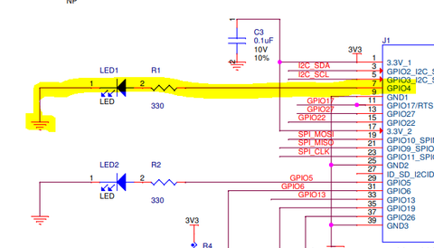
LED stands for Light Emitting Diode and glows when electricity is passed through it.
The LED has one leg that is longer than the other. The longer leg (known as the ‘anode’), is always connected to the positive supply of the circuit. The shorter leg (known as the ‘cathode’) is connected to the negative side of the power supply, known as ‘ground’. LEDs will only work if power is supplied the correct way round (i.e. if the ‘polarity’ is correct).
GPIO stands for General Purpose Input Output. It is a way the Raspberry Pi can control and monitor the outside world by being connected to electronic circuits. The Raspberry Pi is able to control LEDs, turning them on or off, motors, or many other things. It is also able to detect whether a switch has been pressed, temperature, or light. In the CamJam EduKit, you will learn to control LEDs and a buzzer, and detect when a button has been pressed.
In Schematics, it is directly connected to Pin 7 of the 40 Pin Connector. This corresponds to the GPIO4 pin.
This is the location of the Green LED on the board.

Following python code can be used to turn the LED on or off.
1 2 3 4 5 6 7 8 9 10 |
import RPi.GPIO as GPIO import time GPIO.setmode(GPIO.BCM) GPIO.setwarnings(False) GPIO.setup(4,GPIO.OUT) print "LED on" GPIO.output(4,GPIO.HIGH) time.sleep(1) print "LED off" GPIO.output(18,GPIO.LOW) |
Exercise 1 – Turn on Red LED in place of Green LED
Exercise 2 – Turn Green and Red LED ON off Alternatively
Exercise 3 – Turn Green and Red LED ON off Alternatively
7 Segment Display has seven segments in it and each segment has one LED inside it to display the numbers by lighting up the corresponding segments. Like if you want the 7-segment to display the number “5” then you need to glow segment a,f,g,c, and d by making their corresponding pins high. There are two types of 7-segment displays: Common Cathode and Common Anode, here we are using Common Cathode seven segment display.

Now we know how to display our desired numeric character on a single 7-segment display. But, it is pretty evident that we would need more than one 7-segment display to convey any information that is more than one digit. So, in this tutorial, we will be using a 3-digit 7-Segment Display Module as shown below.
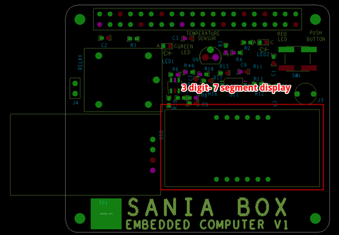
Below is the Schematics for 3 digit-7 segment display.

Following python code can be used to turn the LED on or off.
1 2 3 4 5 6 7 8 9 10 11 12 13 14 15 16 17 18 19 20 21 22 23 24 25 26 27 28 29 30 31 32 33 34 35 36 37 38 39 40 41 42 43 44 45 46 47 48 49 50 51 52 53 54 55 56 57 58 59 60 61 62 63 64 65 66 67 68 69 70 71 72 73 74 75 76 77 78 79 80 81 82 83 84 85 86 87 88 89 90 91 92 93 94 95 96 97 98 99 100 101 102 103 104 105 106 107 108 109 110 111 112 113 114 115 116 117 118 119 120 121 122 |
import RPi.GPIO as GPIO
import time, datetime

now = datetime.datetime.now()

GPIO.setmode(GPIO.BCM)
GPIO.setwarnings(False)

 #GPIO ports for the 7seg pins
segment8 =  (26,19,13,6,5,11,9,10)


for segment in segment8:
    GPIO.setup(segment, GPIO.OUT)
    GPIO.output(segment, 0)

    #Digit 1
    GPIO.setup(7, GPIO.OUT)
    GPIO.output(7, 0) #Off initially
    #Digit 2
    GPIO.setup(8, GPIO.OUT)
    GPIO.output(8, 0) #Off initially
    #Digit 3
    GPIO.setup(25, GPIO.OUT)
    GPIO.output(25, 0) #Off initially
    #Digit 4
    GPIO.setup(24, GPIO.OUT)
    GPIO.output(24, 0) #Off initially

null = [0,0,0,0,0,0,0]
zero = [1,1,1,1,1,1,0]
one = [0,1,1,0,0,0,0]
two = [1,1,0,1,1,0,1]
three = [1,1,1,1,0,0,1]
four = [0,1,1,0,0,1,1]
five = [1,0,1,1,0,1,1]
six = [1,0,1,1,1,1,1]
seven = [1,1,1,0,0,0,0]
eight = [1,1,1,1,1,1,1]
nine = [1,1,1,1,0,1,1]

def print_segment(charector):
    if charector == 1:
        for i in range(7):
            GPIO.output(segment8[i], one[i])

    if charector == 2:
        for i in range(7):
            GPIO.output(segment8[i], two[i])

    if charector == 3:
        for i in range(7):
            GPIO.output(segment8[i], three[i])

    if charector == 4:
        for i in range(7):
            GPIO.output(segment8[i], four[i])

    if charector == 5:
        for i in range(7):
            GPIO.output(segment8[i], five[i])

    if charector == 6:
        for i in range(7):
            GPIO.output(segment8[i], six[i])

    if charector == 7:
        for i in range(7):
            GPIO.output(segment8[i], seven[i])

    if charector == 8:
        for i in range(7):
            GPIO.output(segment8[i], eight[i])

    if charector == 9:
        for i in range(7):
            GPIO.output(segment8[i], nine[i])

    if charector == 0:
        for i in range(7):
            GPIO.output(segment8[i], zero[i])

    return;

while 1:

    now = datetime.datetime.now()
    hour = now.hour
    minute = now.minute
    h1 = hour/10
    h2 = hour % 10
    m1 = minute /10
    m2 = minute % 10
    print (h1,h2,m1,m2)


    delay_time = 0.001 #delay to create virtual effect


    GPIO.output(7, 1) #Turn on Digit One
    print_segment (h1) #Print h1 on segment
    time.sleep(delay_time)
    GPIO.output(7, 0) #Turn off Digit One

    GPIO.output(8, 1) #Turn on Digit One
    print_segment (h2) #Print h1 on segment
    GPIO.output(10, 1) #Display point On
    time.sleep(delay_time)
    GPIO.output(10, 0) #Display point Off
    GPIO.output(8, 0) #Turn off Digit One

    GPIO.output(25, 1) #Turn on Digit One
    print_segment (m1) #Print h1 on segment
    time.sleep(delay_time)
    GPIO.output(25, 0) #Turn off Digit One

    GPIO.output(24, 1) #Turn on Digit One
    print_segment (m2) #Print h1 on segment
    time.sleep(delay_time)
    GPIO.output(24, 0) #Turn off Digit One

    #time.sleep(1)
|
Once you have mastered basic functions you can start experimenting with advanced features of the Sania Board. Get familiar with Analog to Digital Converters. We have an MCP3002 Analog to Digital Converter on Board. To show how it works, we have included a photo Resistor PDV-P8104. As the light intensity incident on it changes, the value of the resistor and hence the voltage input to MCP3002 changes. This can be read by Raspberry Pi.
Following is the schematic of the light sensor connected to Raspberry pi.

This is the location of the Light sensor on the board.

Following python code can be used to turn the Light Sensor.
1 2 3 4 5 6 7 |
import RPi.GPIO as GPIO

GPIO.setmode(GPIO.BCM)
GPIO.setup(4,GPIO.IN)

for i in range(0,5):
    print GPIO.input(4)
|
MQ-135 Gas SensorThe MQ-x series of smoke detectors work well with Raspberry Pi. These sensors, the MQ-135 and MQ-7 have an analog and digital output. Herein, we’ll use the digital output pin labeled d0 on the sensor to output a warning if CO(i.e., smoke) is detected. Alternatively, the analog output could be used to measure the level of CO, but this will need an analog/digital converter like MCP3008.
This is Schematics and its potential use.

This is the location of the Gas Sensor on the board.

Following python code can be used to use the gas sensor.
1 2 3 4 5 6 7 8 9 10 11 12 13 14 15 16 17 18 19 20 21 22 23 |
# the sensor has to be connected to pin 1 for power, pin 6 for ground
# and pin 7 for signal(board numbering!).

import time, sys
import RPi.GPIO as GPIO

GPIO.setmode(GPIO.BOARD)
GPIO.setup(7, GPIO.IN, pull_up_down=GPIO.PUD_DOWN)

def action(pin):
    print('Sensor detected action!')
    return

GPIO.add_event_detect(7, GPIO.RISING)
GPIO.add_event_callback(7, action)

try:
    while True:
        print('alive')
        time.sleep(0.5)
except KeyboardInterrupt:
    GPIO.cleanup()
    sys.exit()
|
The thermal/temperature sensor is perfect for projects like weather stations and home automation systems. Few sensors are this easy to set up on the Raspberry Pi. They’re the same size as a transistor and use only one wire for the data signal. They’re also extremely accurate and take measurements quickly. The only other component you need is a 4.7K Ohm or 10K Ohm resistor.
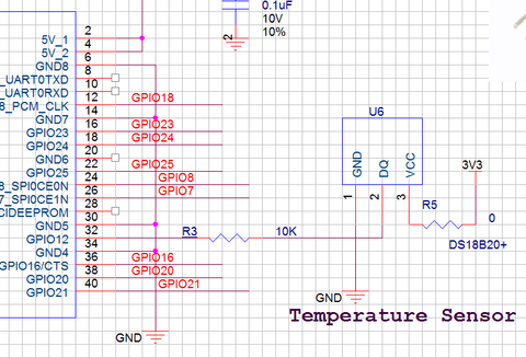
This is the location of the Temperature sensor on the board.

Following python code can be used to run the temperature sensor and display temperature on the terminal.
1 2 3 4 5 6 7 8 9 10 |
import os
import glob
import time

os.system('modprobe w1-gpio')
os.system('modprobe w1-therm')

base_dir = '/sys/bus/w1/devices/'
device_folder = glob.glob(base_dir + '28*')[0]
device_file = device_folder + '/w1_slave'
|
Capacitive touch breakout boards are an excellent way to use household objects as inputs on your Raspberry Pi. Any conductive object can act as a switch when connected to sensor boards, including potatoes, apples, spoons, and pencil graphite.
The capacitive touch sensors detect when you touch the board’s pad or an object connected to the board. Humans carry a small electrical charge. When you touch a capacitive touch sensor it will detect this charge.
This is the Schematics corresponding to the Touch Sensor. The GPIO8 Input Pin of the Rasberry Pi Changes its state depending on if the touch crosses the threshold or not.

This is the location of the Touch sensor on the board.

1 2 3 4 5 6 7 8 9 10 11 12 13 14 15 |
import time
import board
from digitalio import DigitalInOut, Direction

pad_pin = board.D23

pad = DigitalInOut(pad_pin)
pad.direction = Direction.INPUT

while True:

if pad.value:
print("pressed")

time.sleep(0.1)
|
Audio Buzzer
An on board Audio Buzzer can be used to give an alarm sound.
The Schematics of the Alarm
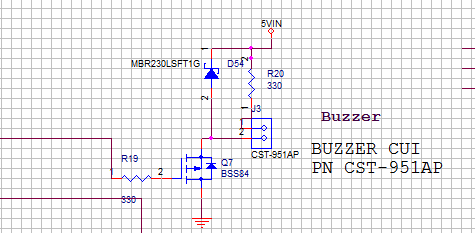
This is the location of the Buzzer and Relay on the board.

The Buzzer can be activated by sending a digital 300 Hz to about 10K square wave to GPIO37.
A relay is an electrically operated switch. These switches can be extremely useful for a variety of Raspberry Pi projects (think turning on a light or opening your garage door. Watch the video below to learn how to drive a relay using your Raspberry Pi.
The following schematics show how the Relay is connected to Raspberry Pi.

Following python code can be used to turn the Relay switch On and Off.
1 2 3 4 5 6 7 8 9 10 11 12 13 14 15 |
#!/usr/bin/env python import time import RPi.GPIO as GPIO GPIO.setmode(GPIO.BCM) GPIO.setup(17, GPIO.OUT) GPIO.output(17, GPIO.LOW) time.sleep(0.25) GPIO.output(17, GPIO.HIGH) GPIO.cleanup() |

Vikas Shukla, an innovator at heart whose undivided attention is dedicated to technology. His inquisitiveness to create has led to several innovations in the field of hardware and software. He is the architect behind several successful learning products for students. These tool kits are a part of the curriculum at Moonpreneur.
